Wow you are awesome for doing all that sim work for me/the forum 🙂)), I can't quite understand akabak's format but I know it's much more accurate 🙂. One thing is the driver is rated for 250 watts and 10 MM xmax (although xdmg is much higher). Limited to 34 V for this reason. I may try throwing more power at it but I like to error on the safe side. Also, this sim shows that throwing a sub in a corner =/= 12 dB across the board but rather changes the response to a degree. Thanks again for taking the time to dimension that out.
Oh and port length (the wood pieces) is 4.5 inches, fairly exactly as cut.
Oh and port length (the wood pieces) is 4.5 inches, fairly exactly as cut.
Last edited:
What I am confused by is why hornresp gives me a 2.5 dB peak at 37-38 Hz when akabak just rolls off 🙁.
Don't get me wrong I love that I should be able to get 115 dB flat to 40 and 113 to 35 disregarding corners, just was expecting 117 at 38. On the bright side, it's flatter than expected and has more mid-high bass (60-80) than I thought.
I really want to learn akabak for future designs because of the realistic corned loaded sim capability.
What I am confused by is why hornresp gives me a 2.5 dB peak at 37-38 Hz when akabak just rolls off 🙁.
Don't get me wrong I love that I should be able to get 115 dB flat to 40 and 113 to 35 disregarding corners, just was expecting 117 at 38. On the bright side, it's flatter than expected and has more mid-high bass (60-80) than I thought.
I really want to learn akabak for future designs because of the realistic corned loaded sim capability.
I think Akabak has the same peak you see when looking at the 2pi case, it is the peak which is the start of the saddle. This peak goes away with boundary loading like back wall or corner. I also added some 'damping' in the first half of the line and this may suppress peak a bit. I assume you have some damping in there (most ML-TL's use damping).
That is why I posted the Akabak script. Download and install Akabak and run the script. Play around with the walls and corner loading. I commented it heavily to help folks get started in using it.I really want to learn akabak for future designs because of the realistic corned loaded sim capability.
0 dampening here 🙂
Also, I can't run akabak (64 bit windows). So unfortunate.
Install a virtual Windows XP machine inside Win64 and install Akabak there. That is how I am using it. There are several packages like VMWare, etc. If you have Win7 Enterprise, MS provides a free WinXP virtual machine via download.
Or dig out an old PC/laptop (pre win 64) and use for Akabak only.
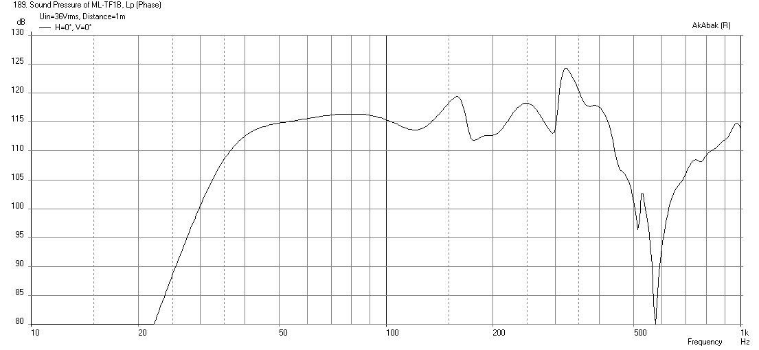
Here is the baseline simulation of the SPL vs freq in 2pi space with no HPF or LPF's applied. Here we can see that location of the 40Hz bass extension and the sharp dips at 180Hz, 210Hz, and 450Hz correspond well to measurement by Sabaspeed:
[/CODE]
Fantastic!
Xrk , Thanks for the Sim work with Akabak and also for making the script available 🙂
Do you suppose that general hump in response between 320hz and 450hz is the plenum (small bandpass chamber) resonance? I have another version of this ML-TP cab that should shift that resonance down to where it is more beneficial.. Unfortunately Hornresponse doesn't seem to factor-in that additional resonance properly for some reason so it looks like Akabak is the way to go in order to see whether there will be any useful extended midbass response above the of the main pipe's third harmonic ...
Last edited:
Revised script with damping in first half and turn
No, that resonance corresponds to a circa 30 in long 1/4-wave resonance which means it is internal. HR should capture this. I shortened the plenum to 0.5 in and the same 350-450hz bump is still there.
I caught a small typo in how I labeled the nodes on Waveguide4 (basically did not account for extra path of 1 of the 4 x 45deg turns at the top). Here is the revised script with that typo fixed. It did not affect final results much as that was a 2.6in long segment. I also added viscous damping in first leg of TL and damping in the 180 deg turn. This helps to smooth the response out giving it response out to 400Hz. If you were to EQ those bumps you could use this as a bass and midbass speaker. I also set xmax to 10mm so max volts is now 36v.
Here is the predicted SPL vs freq at xmax with no low pass filter, only 33Hz HPF:
Here is predicted response without damping:

Here is the revised code which fixes typo and adds damping:
Do you suppose that general hump in response between 320hz and 450hz is the plenum (small bandpass chamber) resonance? I have another version of this ML-TP cab that should shift that resonance down to where it is more beneficial.
No, that resonance corresponds to a circa 30 in long 1/4-wave resonance which means it is internal. HR should capture this. I shortened the plenum to 0.5 in and the same 350-450hz bump is still there.
I caught a small typo in how I labeled the nodes on Waveguide4 (basically did not account for extra path of 1 of the 4 x 45deg turns at the top). Here is the revised script with that typo fixed. It did not affect final results much as that was a 2.6in long segment. I also added viscous damping in first leg of TL and damping in the 180 deg turn. This helps to smooth the response out giving it response out to 400Hz. If you were to EQ those bumps you could use this as a bass and midbass speaker. I also set xmax to 10mm so max volts is now 36v.
Here is the predicted SPL vs freq at xmax with no low pass filter, only 33Hz HPF:
Here is predicted response without damping:
Here is the revised code which fixes typo and adds damping:
Code:
| ML-Transflex designed by Matthew Morgan L @diyAudio.com
| with Dimensions 'as-built' by Sabaspeed521 @diyAudio.com
| modeled by xrk971 @diyAudio.com
| Aug 19, 2014
| version ML-TF1B, fixed typo on WG4 node, added stuffing in 180 turn and first section of TL

Def_Const
{

| *** these dimensions are used for diffraction/reflection analysis ***
Speaker_pos=6.075*0.0254;  | Height of centerline of exit port above floor
Width_ext=13.5*0.0254;  | Width of cabinet external
Height=31.0*0.0254; | Height of cabinet external
Depth=13.375*0.0254;  | Depth of cabinet
Dist_wall=70*0.0254;  | Distance from wall  (70 in gives flat response)

| *** specify internal cabinet panel width here***
Width=12.0*0.0254;  | internal width

}

Def_Driver  'Alpine SWE-10S4-M' | 10 in Qts 0.6307, T/S params measured by Sabaspeed, xmax=10mm, xdamage=25mm
  SD=345cm2   |Piston
  fs=41.7Hz
  Mms=111.3g
  Qms=6.754
  Qes=0.6956
  Re=3.88ohm
  Vas=21.82L
  Bl=12.79Tm

Def_Driver  'Alpine SWE-10S4' | 10 in Qts 0.51, 87dB sens Factory specs, xmax=10mm, xdamage=25mm
  SD=356cm2   |Piston
  fs=40.0Hz
  Mms=111.3g
  Qms=6.75
  Qes=0.55
  Re=3.60ohm
  Le=1.70mH
  Vas=26L

System 'ML-TransFlex-B'

| *** Specify high pass and low pass filters here, remove comment bar in front of OFF to turn on

|OFF
Filter    'High Pass'  | 4th order Butterworth -24dB/oct
    fo=33Hz  vo=1.0
    {b4=1;
     a4=1;  a3=2.613126;  a2=3.414214;  a1=2.613126;  a0=1;  }
OFF
Filter 'LowPass' |Lowpass filter - 48dB Butterworth (change 'fo=***' and refresh for changes)
fo=100Hz vo=1
{b0=1;
a8=1; a7=5.125831; a6=13.137071; a5=21.846151; a4=25.688356; a3=21.846151; a2=13.137071; a1=5.125831; a0=1; }

| *** specify rear wall loading (assumes only back wall and floor have reflection effect)
OFF
| Speaker placed in corner with driver at Driver_pos above floor in corner x dist away from walls
Def_Reflector  BottomCorner
Bottom={Speaker_pos}  Left=20in Right=20in
HAngle=0  VAngle=0

| *** specify corner loading (assumes floor and two side walls have reflection effect ***
|OFF
| Speaker with driver at Driver_pos above floor Dist_wall away from wall
Def_Reflector  HorizEdge
Bottom={Speaker_pos}  Top={Depth + Dist_wall}
HAngle=0  VAngle=0

Driver Def='Alpine SWE-10S4-M' 'Driver 1'  | specify factory or measured T/S params here
Node=1=0=11=19  | driver face at node=11, driver back at node=17, amp is node=1, ground is node=0

|  *** begin model of TL ***

Duct    'D1'  Node=10=11  | from closed end to driver face
  WD={Width}  HD=5.25in  Len=5.375in  Visc=20  | Visc=20 used to represent moderate to heavy stuffing

Duct    'D2'  Node=11=12  | from driver to begining of turn
  WD={Width}  HD=5.25in  Len=18.125in  Visc=20

| *** turns modeled as 45 deg expansion followed by 45 deg contraction ***

Waveguide    'W3'  Node=12=13  | first 45 deg turn (expansion)
  WTh={Width}  HTh=5.25in
  WMo={Width}  HMo=7.97in
  Len=3.00in
  Conical
  AcouResistance    'Stuffing12'  Node=12=13  Ra=7e3Pas/m3  | Simulate moderate stuffing

Waveguide    'W4'  Node=14=13  | second 45 deg turn (contraction) note reverse nodes
  WTh={Width}  HTh=6.00in
  WMo={Width}  HMo=7.97in
  Len=2.625in
  Conical
  AcouResistance    'Stuffing13'  Node=14=13  Ra=70e3Pas/m3  | Simulate moderate stuffing

Duct    'D45'  Node=14=15  | divider thickness between turns
  WD={Width}  HD=6.00in  Len=0.75in

Waveguide    'W5'  Node=15=16  | third 45 deg turn (expansion)
  WTh={Width}  HTh=6.00in
  WMo={Width}  HMo=8.397in
  Len=2.938in
  Conical
  AcouResistance    'Stuffing15'  Node=15=16  Ra=70e3Pas/m3  | Simulate moderate stuffing

Waveguide    'W6'  Node=17=16  | fourth 45 deg turn (contraction) note reverse nodes
  WTh={Width}  HMo=8.937in
  WMo={Width}  HTh=5.875in
  Len=3.00in
  Conical
  AcouResistance    'Stuffing16'  Node=17=16  Ra=70e3Pas/m3  | Simulate moderate stuffing

Duct    'D7'  Node=17=18  | from turn to ML constrictor port (expansion)
  WD={Width}  HD=5.875in  Len=8.25in

Duct    'D8'  Node=18=19  | model constrictor port as simple straight duct (skip model of hairpin turns)
  WD={Width}  HD=1.50in  Len=13.25in

Duct    'D9'  Node=19=20  | exit duct leading to mouth driver back at node=19
  WD={Width}  HD=10.75in  Len=5.875in

| *** specify radiator as exit node of final mouth duct ***

Radiator 'Duct_rad'
Def='D9'
Node=19
| *** comment out following lines if no baffle diffraction desired and no reflections desired
x=0  y=0  z=0
HAngle=0  VAngle=0
WEdge={Width_ext/2}  Hedge={Height}
Reflection
Attachments

Last edited:
BeauB,
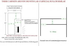
Here is another sketch with some more explanation and details of measurements on the ML-TRANSFLEX for the Eminence 15 (special run) ...
.....
I think i might arrange version 2 of the 50 liter cabinet for the Alpines in this same manner, with the constriction/port placed at the top right of the internal divider/baffle panel ... The cab sims a little better that way, and gives us slightly more path length while only increasing the total cab size by a few liters... This arrangement is also more likely to place any additional bandpass resonance (developed by the small chamber being energized from rear of the cone) closer to where it is needed which will be between the 3rd and 5th harmonic of the box's main pipe resonance...


Some of these numbers seem to contradict each other, is it 33 tall 18 wide (meaning side to side) and 18.75 deep? I believe this would keep the equal volume contour of the pipe intact. Correct me if I'm mistaken, trying to cad it out now.
That resonance corresponds to a circa 30 in long 1/4-wave resonance which means it is internal. HR should capture this.
[/CODE]
Ok, I think i understand what you are saying ...Does Akabak take the folding into account? If so then it would explain why HR doesn't really show that significant bump there while your Akabak sim definitely does show it.....
Saba's wide range unfiltered measurement seems to tell a different story, where everything in that upper range looks so much more subdued and insignificant as if the attenuating effects of driver inductance are really coming into play up there ....
By the way, thanks for simming with damping material, i was curious about how adding some damping material might work out since stuffing/lining (especially in the first 25% to 33% of the path) can be so beneficial to a traditional ML-TL and TLs in general..
I modeled the ML-Transflex 180 deg turn using the standard technique of an expansion-contraction-expansion-contraction in CSA. This introduces places for impedance changes and acoustically it will be different than a smooth TL.
AkAbak assumes a perfect pistonic driver in this case (you can model more complex diaphragms that are concave and flex) so in reality will probably not have response as high. I am not sure if Sabaspeed was applying any filters up on top.
AkAbak assumes a perfect pistonic driver in this case (you can model more complex diaphragms that are concave and flex) so in reality will probably not have response as high. I am not sure if Sabaspeed was applying any filters up on top.
Last edited:
Is it 33 tall 18 wide (meaning side to side) and 18.75 deep? I believe this would keep the equal volume contour of the pipe intact.
Saba, I see the mistake you are pointing out, good catch.
After some fine tuning of the design i was pleased to see that i could reduce the size to around 135 L (the traditional style TP was 144L), I updated the depth on one set of dimensions in the sketch but neglected to change the other set of dimensions .... I will post a fixed sketch for this Eminence design with the correction ....
The 135 liter dimensions are: 33"H x 18"W x 17.5"D
I really like the way this folding works, efficient and simple 🙂
Last edited:
Ok,
Here is an updated sketch of the 135 liter 35hz ML-Transflex originally in post #103
The dimensions conflict is now fixed 🙂
I plan on posting a more comprehensive collage/sketch complete with more detail such as HR inputs, response graph etc ... Similar to what i posted for the Alpine 40hz ML-Transflex recently... The fold is now arranged the same way on both designs.
Attachments
Ok,
Here is an updated sketch of the 135 liter 35hz ML-Transflex originally in post #103
The dimensions conflict is now fixed 🙂
I plan on posting a more comprehensive collage/sketch complete with more detail such as HR inputs, response graph etc ... Similar to what i posted for the Alpine 40hz ML-Transflex recently... The fold is now arranged the same way on both designs.
Wonderful, looks brilliant, can't wait to try out, seems I will want handles on this one or building it out of 1/2 inch (with 3/4 or double 1/2 inch baffle) with more extensive bracing as it should be in the neighborhood of 90-100 pounds with the much beefier driver and ~40% larger volume.
P.S. I did some cost analysis on the ML-TL that I built and assuming you have to buy all consumables the prices (for me) were as follows:
2 sheets of 4x8 per 3 cabs = 40*2 = 80 total or 80/3 = 27 rounds to 30 after tax per cab
Driver: 49.95 shipped and tax free
PL premium 2 tubes per cab = 5*2 = 10 ; Should actually only need 1 tube without trim
Mounting gear: 8 washers, t-nuts, #8x32 1.25 inch long bolts = 5 bucks at Home Depot
insignificant amount of epoxy ~0
Sanding discs for orbit sander 2x80 grit - not sure on price
Paint - Duratex - 6 cabs per gallon = 10 $ each after shipping/tax
Screws for holding panels in place while building ~ 10 screws - had scrap ones 1.25 inches and 2+ inches long, re-usable ~0
= ~105 altogether.
Things I didn't buy but most likely others will:
Neutrik NL4MP-ST Speakon Connector 4 Pole Panel Mount
Terminals, need 2 so 6.60+ S&H, not including speakon cables here because indirect.
Handles (not needed, I just bear hug it holding the ends and the mouth IMO but preference) Check penn elcom, haven't bought handles ever I usually cut them into the wood in isolated chambers
Substitute more expensive SWS and you're looking at 135-140 depending on tax (total cost)
The Eminence box should be well worth the effort! 🙂 and will likely sound very similar to your Alpine box, just bigger and louder! 
Last edited:
Ok,
Here is an updated sketch of the 135 liter 35hz ML-Transflex originally in post #103
The dimensions conflict is now fixed 🙂
I plan on posting a more comprehensive collage/sketch complete with more detail such as HR inputs, response graph etc ... Similar to what i posted for the Alpine 40hz ML-Transflex recently... The fold is now arranged the same way on both designs.
Once I have the CAD done to convert this to 3D tell people to PM me if they want the solidworks files, unless you want to restrict rights on the design but this is DIYaudio so I thought I might as well give them away over PM (rather than upload them). I won't be disappearing anytime soon from this forum as I have already learned so much!
It should be well worth the effort! 🙂 and should sound similar to your Alpine box, just bigger and louder!
Right now I'm just trying to get my money back from the first two, so I can buy 2 of the lab drivers. Person who "ordered them" I trust as a good friend but he has been impossible to reach lately. I'll call his parents if I don't hear back in a week (doesn't live with them but maybe his number has changed).
I just noticed that the same depth dimension flaw was included in a comparison sketch found at Post #83 ...... Here is a fixed version of that sketch ... Luckily it is really not an end-of-the-world level mistake because if someone were to build this box one inch too deep it would still work just fine, no problem (thankfully nobody would have wasted their time, money and ply), but nevertheless it would be nice if the administrators of this forum would allow users to go back and edit old posts when we spot blunders like these, even if they aren't necessarily critical errors ...
Attachments

Last edited:
I just noticed that the same depth dimension flaw was included in a comparison sketch found at Post #83 ...... Here is a fixed version of that sketch ... Luckily it is really not an end-of-the-world level mistake because if someone were to build this box one inch too deep it would still work just fine, no problem (thankfully nobody would have wasted their time, money and ply), but nevertheless it would be nice if the administrators of this forum would allow users to go back and edit old posts when we spot blunders like these, even if they aren't necessarily critical errors ...
How does one bolt in the driver? Haha I was just thinking of how I would have to bend my arm to tighten this down/mount (getting it in at an angle wouldn't be tooo bad, just the screw portion).
How does one bolt in the driver? Haha I was just thinking of how I would have to bend my arm to tighten this down/mount (getting it in at an angle wouldn't be tooo bad, just the screw portion).
Saba,
Since the magnet will be in the mouth you can actually make the mouth cm sq area larger than the pipe area (824cm sq or only about 7-5/8") ... The magnet and basket take up space there creating some additional mass loading and in order to compensate you can simply open up the mouth some more 🙂 ... So in the end it all works out because you can likely make the mouth opening 9 to 13" tall (maybe a little more) without shifting the FB of the box up too much above the target FB ..... An impedance measurement of the box can be used to determine where your fundamental ends up...... In the worst case scenario, if you have opened up the mouth as much as possible (don't want to detune the box by opening up the mouth any further) and still find it awkward to access the screws then you could just add a small access panel above the mouth..
- Home
- Loudspeakers
- Subwoofers
- New sub design? Constricted Transflex, simple build (series tuned 6th order)