Not sure if you're trolling me but the reality is in stacks it plays flat to 31... Can be built easily with no difficult parts (i.e. fast) and is designed with the portable DJ in mind -- not home theater.
Apologies if I misinterpreted your post, It really is in a class of its own (compact PA with extension) All the other designs I've seen choose output over extension and in reality extension can make or break a fair number of newish songs. Nothing worse than a club with a 50 Hz HP playing Hip-Hop.
that's ok - just saying a sub/sound system in the car I bought some years back would not work with its exhaust and tiny trunk (that's its former owner) http://i.imgur.com/rbsJVms.jpg
That car luckily needs no sound system 🙂. Yeah I never thought of it but this sub would make a decent car sub, but I doubt you'd use the power, sooner build a sealed box in that case.
what did I botch on copying one of the hornresp models to get the result below?
how is the constriction shown in hornresp? - this type should translate to goodly number of woofers
-think I got the input window from http://www.diyaudio.com/forums/subw...ld-series-tuned-6th-order-12.html#post4028379
maybe I somehow got hornresp into a glitch - is that possible? - just ran again and got a reasonable result
Last edited:
Freddi ,
Click on "tools" at the top left of Hornresponse and go to "chamber type" and choose "throat ported" ...
Those inputs are for the most recent version of the 40hz box .... Saba's version was scaled up a little with an FB of 35hz ...
Click on "tools" at the top left of Hornresponse and go to "chamber type" and choose "throat ported" ...
Those inputs are for the most recent version of the 40hz box .... Saba's version was scaled up a little with an FB of 35hz ...
Last edited:
A few of those dimensions are different from what they should be iirc. LE is 2.42, ATC 445, vtc 45k or so and the conical connector segments are different. same goes for the port size and length.
Freddi ,
To answer your question about the constriction/port , it is defined by "Ap1" and "Lpt"
To answer your question about the constriction/port , it is defined by "Ap1" and "Lpt"
thank you very much - I'd love to have this design but already have about 30 cabinets 2 many 😀 -if I had room, a version for my old Dayton 295-070 might be good. Is there a way to apply this in a useful fashion to a "regular Karlson" cabinet?
Last edited:
Don't we all 🙂 I have a total of 5 speakers 5 or 6 subs and lots more subs planned 🙂. Plan is to get a quad stack of lab 15 loaded MLTP's so I can do modest outdoors events and crazy indoors ones.
Just noticed but 58 volts may be a bit much for the LAb 15 as that correlates to a max power of 750 watts. Granted that wouldn't destroy the VC unless sustained and basically sine wave but some music has crazy duty cycle. I'd say 50 Volts is safer.
Saba ,
Freddi grabbed the right inputs for the updated 40hz cab, just needed to switch his throat chamber setting under "tools" in HR .... The raised Le is something i do in sims, as a sort of lossy cabinet compensation strategy, trying to better sim the real world results .....
In the most recent version of the 40hz box i shifted the constriction up the path a little, so the pipe segments (where the magnet side of the woofer resides) have additional length and the throat chamber itself is a little shorter .... Length and area of the constriction stay the same ... It is now arranged to look like a miniature version of the LAB 15 special edition loaded ML-TP ...
Saba, can you post the input screenshot for your 35hz version? I would like to add it to my HR records🙂
Last edited:
the little Alpine version looks pretty strong compared to a 149 liter airspace tapped pipe with 15 " I made 5 years ago
what would the little Alpine sub made of 1/2" Baltic birch weigh?

what would the little Alpine sub made of 1/2" Baltic birch weigh?
The driver I used is a car subwoofer, It's a few pages back but it's the alpine swe-10s4 and it has better performance per cubic foot that any 1260 design I've seen due to the cabinet size requirement discrepancy, even better however is the sws 10d4 and the lab 15 (special run) though.
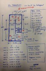
Also, the port lengths are labeled. The width between those two panels is 6 inches, the distance between ports is also labeled, takes a little math but you can do it.
Thanks for the drawing. For the life of me, I still can't back out the distance of each of the vent constrictor pieces. Note that with cad drawings, even if all info can be derived from math, it is often best to put dimension on critical part such as any dimension related to one of the length segments in the HR model to prevent confusion.
Thanks
X
Just noticed but 58 volts may be a bit much for the LAb 15 as that correlates to a max power of 750 watts. Granted that wouldn't destroy the VC unless sustained and basically sine wave but some music has crazy duty cycle. I'd say 50 Volts is safer.
Saba ,
The reason i went higher with the voltage is because the 3.75 ohm "Re" is pretty high for a 4 ohm woofer ..... Considering as an example that various so called "8 ohm" drivers can have an RE figure ranging from as low as 5 ohms to as high as 7.9 ohms (depending on make & model) which can lead to some really misleading simulation results!😱
I generally use a multiplier of 1.5 for comparing different drivers in Hornresponse when calculating the impedance so that it evens out the playing field and does not give drivers with a low-ish RE an unfair SPL advantage over drivers with a higher RE........ This special edition Lab 15 is actually more along the lines of a 5.5 ohm driver ........ It may not be a perfect system but this is how i came up with the 58v :
RE*1.5= IMPEDANCE ... 58 volts at 5.625 ohms impedance is around 600 watts
Last edited:
When simulating for peak SPL capability, use voltage that reaches xmax, and when simulating for max RMS output (sustained sine wave output indefinitely) use voltage that provides max thermal power rating per manufacturer's spec. When comparing sensitivity, use either 2.83v or 1watt at 1m. There is a gray area if the driver has huge xdamage vs xmax like some with xmax (linear) of 12mm but xdamage of 25mm. You can then simulate for a high peak SPL assuming you are able to ignore the large distortion but stay below xdamage.
I typically run sims until xmax is reached for RMS input. The Re is accounted for in the model of the driver and so I do not see why one would apply an arbitrary 1.5x factor to "even things out". It is like saying one driver has a higher BL (a function of magnet and pole piece geometry) and applying a factor to even things out. The T/S parameters define a driver so that we can model and compare them. When predicting max sustaiend SPL, it should be based on combination of xmax and max AES rated thermal power. Sometimes AES max is reached before xmax (rarely).
I typically run sims until xmax is reached for RMS input. The Re is accounted for in the model of the driver and so I do not see why one would apply an arbitrary 1.5x factor to "even things out". It is like saying one driver has a higher BL (a function of magnet and pole piece geometry) and applying a factor to even things out. The T/S parameters define a driver so that we can model and compare them. When predicting max sustaiend SPL, it should be based on combination of xmax and max AES rated thermal power. Sometimes AES max is reached before xmax (rarely).
Xrk,
Like i said, i know it is not a perfect method, but from experience i do believe it to be more accurate when comparing various drivers that have wildly different RE figures even though they may all be referred to as "8 ohm" according to the manufacturer, the truth is that they aren't EXACTLY 8 ohm (or 4 ohm or whatever) ...

When clicking on the Eg field in Hornresponse the box pops up asking for both "power in watts" and "load impedance in ohms" it helps to be able to enter in a more specific impedance figure rather than just typing in an oversimplified 4 ohms or 8 ohms.... Entering in a more specific impedance assists Hornresponse in calculating the proper drive voltage and puts drivers with various RE figures on a reasonably "even playing field"...
You don't have to believe me though, you can easily test this for yourself ..... Create two simple identical cabinets with drivers that have that exact same QTS/QES/QMS, FS, VAS, SD, moving mass and so on but give one an RE of 5 ohms and the other an RE of 7.5 ohms (The driver with the higher RE will require a slightly higher BL in order to maintain the same QES/QTS , but that is normal) ...... So, ok, once you have created your test drivers/boxes go ahead and click on the "Eg" field and be sure to enter the same impedance and watts for both drivers and behold the difference in "acoustic power" output ...... It is significant .... The driver with higher RE appears to be less efficient in the simulation but it isn't really, it is in fact equally as efficient in actuality, it just requires more voltage to reach the same power level because it draws less current, thats all ...... Voltage multiplied by current equals wattage....
So now go back and calculate the impedance from the RE figures on each test driver by multiplying by 1.4 or 1.5 .... So 5*1.4 = 7 ohms, and 7.5*1.4 = 10.5 ohms, now enter those impedance figures into the corresponding impedance field(the popup box you get when you click on Eg) of each test cabinet along with a matching "Power in Watts" figure on both cabs ...After clicking on "ok" you will see that a different voltage is applied to each cabinet but the "Acoustic Power" output and xmax simulate EXACTLY the same now ! 😀
Does this make me "Captain Obvious"? Im sure many of you already knew about this, but for those who didn't know i will summarize: You cannot expect Hornresponse to magically generate accurate drive voltages based on an overly vague impedance entry when that entry is used as a reference, so in my opinion it helps a lot to be more specific.. .. *end of rant*
Like i said, i know it is not a perfect method, but from experience i do believe it to be more accurate when comparing various drivers that have wildly different RE figures even though they may all be referred to as "8 ohm" according to the manufacturer, the truth is that they aren't EXACTLY 8 ohm (or 4 ohm or whatever) ...
When clicking on the Eg field in Hornresponse the box pops up asking for both "power in watts" and "load impedance in ohms" it helps to be able to enter in a more specific impedance figure rather than just typing in an oversimplified 4 ohms or 8 ohms.... Entering in a more specific impedance assists Hornresponse in calculating the proper drive voltage and puts drivers with various RE figures on a reasonably "even playing field"...
You don't have to believe me though, you can easily test this for yourself ..... Create two simple identical cabinets with drivers that have that exact same QTS/QES/QMS, FS, VAS, SD, moving mass and so on but give one an RE of 5 ohms and the other an RE of 7.5 ohms (The driver with the higher RE will require a slightly higher BL in order to maintain the same QES/QTS , but that is normal) ...... So, ok, once you have created your test drivers/boxes go ahead and click on the "Eg" field and be sure to enter the same impedance and watts for both drivers and behold the difference in "acoustic power" output ...... It is significant .... The driver with higher RE appears to be less efficient in the simulation but it isn't really, it is in fact equally as efficient in actuality, it just requires more voltage to reach the same power level because it draws less current, thats all ...... Voltage multiplied by current equals wattage....
So now go back and calculate the impedance from the RE figures on each test driver by multiplying by 1.4 or 1.5 .... So 5*1.4 = 7 ohms, and 7.5*1.4 = 10.5 ohms, now enter those impedance figures into the corresponding impedance field(the popup box you get when you click on Eg) of each test cabinet along with a matching "Power in Watts" figure on both cabs ...After clicking on "ok" you will see that a different voltage is applied to each cabinet but the "Acoustic Power" output and xmax simulate EXACTLY the same now ! 😀
Does this make me "Captain Obvious"? Im sure many of you already knew about this, but for those who didn't know i will summarize: You cannot expect Hornresponse to magically generate accurate drive voltages based on an overly vague impedance entry when that entry is used as a reference, so in my opinion it helps a lot to be more specific.. .. *end of rant*
Last edited:
Matthew Morgan,
We are not in disagreement at all. I totally see what you are saying. To compare them apples to apples one should reference to 1 watt (at whatever voltage is required given the Re and impedance). But for practical purposes, people assume that their amplifers can deliver the current or amps needed at whatever voltage and when testing referenced to 2.83v even for "4 ohm" speakers, we all know it is more than 1 watt. Ideally if speakers were 4 ohms exactly it would be 2 watts.
We are not in disagreement at all. I totally see what you are saying. To compare them apples to apples one should reference to 1 watt (at whatever voltage is required given the Re and impedance). But for practical purposes, people assume that their amplifers can deliver the current or amps needed at whatever voltage and when testing referenced to 2.83v even for "4 ohm" speakers, we all know it is more than 1 watt. Ideally if speakers were 4 ohms exactly it would be 2 watts.
Model of ML-TransFlex in Akabak
Well after some detective math work and using assumptions of 0.75 in thick for exterior walls and divider, and 0.5in thick for constrictor channel walls, I came up with the dimensions shown in the attached flow-paths-plan used for the model.
The ML-TransFlex as built and using the Alpine 10SW-4 appears to have a saddle in the response when looking at it in 2pi space. However once you add some boundaries, for example at 70 in away from a back wall, it flattens the response nicely. If corner loading 20in away from side wall (45 deg aimed out), you get a flattened but tilted response.
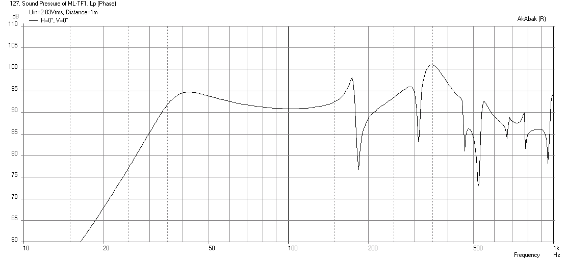
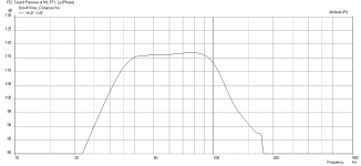
Here is the baseline simulation of the SPL vs freq in 2pi space with no HPF or LPF's applied. Here we can see that location of the 40Hz bass extension and the sharp dips at 180Hz, 210Hz, and 450Hz correspond well to measurement by Sabaspeed:
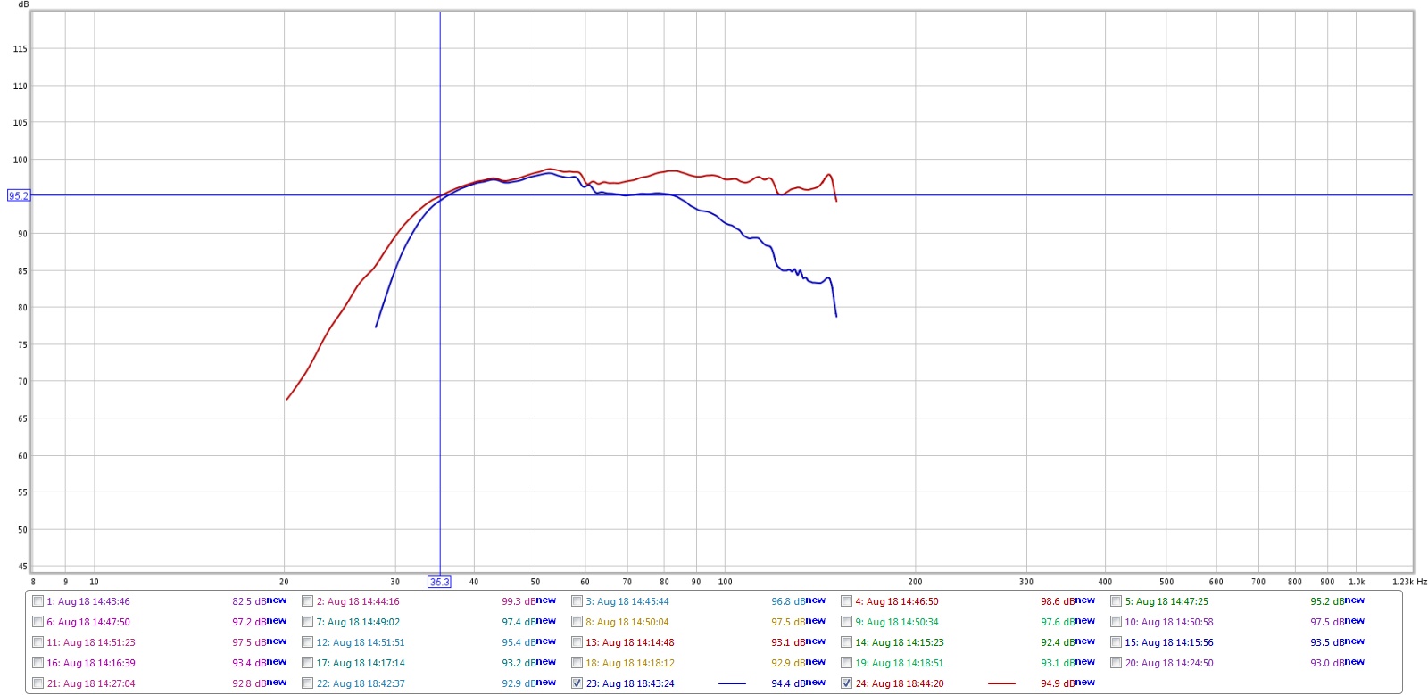
Here is Sabaspeed's measurement (blue is without EQ):
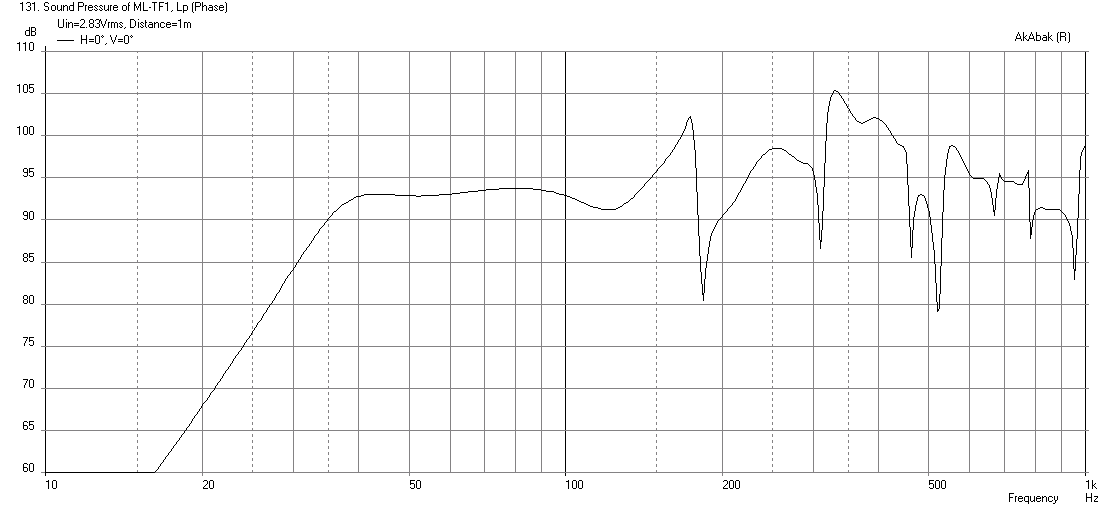
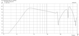
Here is the same but 70 in away from a back wall (sub on wall with mouth centerline 6 in above floor):
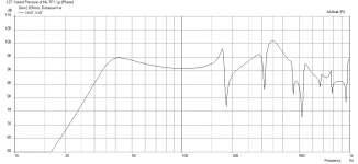
Here is response when placed in corner with mouth 20in away from sidewalls aimed 45 deg out:

We can see that this tilt (-10dB from 40Hz to 100Hz) and the little upward peak at the 170Hz point agrees nicely with the data provided by Sabaspeed.
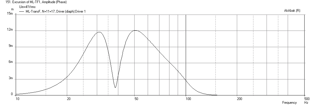
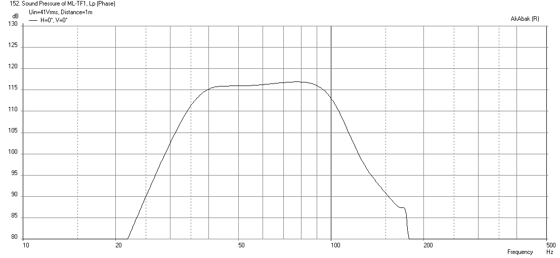
Since the 70in case gives a nice flat and level response, I will use that to see what the max SPL can be. Here is the cone displacement at xmax with a 33Hz -24dB HPF and 100Hz -48dB LPF - it is good for about 117dB at 41volts drive:
Here is corresponding response at xmax:
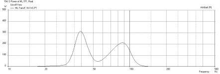
Here is the electrical power required (a little over 300 watts):

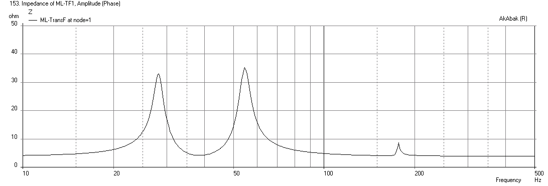
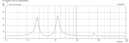
Here is the electrical impedance:
Overall a very nice design and great implementation by Sabaspeed. 🙂
For those interested, here is the code for the Akabak script:
Well after some detective math work and using assumptions of 0.75 in thick for exterior walls and divider, and 0.5in thick for constrictor channel walls, I came up with the dimensions shown in the attached flow-paths-plan used for the model.
The ML-TransFlex as built and using the Alpine 10SW-4 appears to have a saddle in the response when looking at it in 2pi space. However once you add some boundaries, for example at 70 in away from a back wall, it flattens the response nicely. If corner loading 20in away from side wall (45 deg aimed out), you get a flattened but tilted response.
Here is the baseline simulation of the SPL vs freq in 2pi space with no HPF or LPF's applied. Here we can see that location of the 40Hz bass extension and the sharp dips at 180Hz, 210Hz, and 450Hz correspond well to measurement by Sabaspeed:
Here is Sabaspeed's measurement (blue is without EQ):
Here is the same but 70 in away from a back wall (sub on wall with mouth centerline 6 in above floor):
Here is response when placed in corner with mouth 20in away from sidewalls aimed 45 deg out:
We can see that this tilt (-10dB from 40Hz to 100Hz) and the little upward peak at the 170Hz point agrees nicely with the data provided by Sabaspeed.
Since the 70in case gives a nice flat and level response, I will use that to see what the max SPL can be. Here is the cone displacement at xmax with a 33Hz -24dB HPF and 100Hz -48dB LPF - it is good for about 117dB at 41volts drive:
Here is corresponding response at xmax:
Here is the electrical power required (a little over 300 watts):
Here is the electrical impedance:
Overall a very nice design and great implementation by Sabaspeed. 🙂
For those interested, here is the code for the Akabak script:
Code:
| ML-Transflex designed by Matthew Morgan L @diyAudio.com
| with Dimensions 'as-built' by Sabaspeed521 @diyAudio.com
| modeled by xrk971 @diyAudio.com
| Aug 19, 2014

Def_Const
{

| *** these dimensions are used for diffraction/reflection analysis ***
Speaker_pos=6.075*0.0254;  | Height of centerline of exit port above floor
Width_ext=13.5*0.0254;  | Width of cabinet external
Height=31.0*0.0254; | Height of cabinet external
Depth=13.375*0.0254;  | Depth of cabinet
Dist_wall=70*0.0254;  | Distance from wall  (70 in gives flat response)

| *** specify internal cabinet panel width here***
Width=12.0*0.0254;  | internal width

}

Def_Driver  'Alpine SWE-10S4-M' | 10 in Qts 0.6307, T/S params measured by Sabaspeed, xmax=10mm, xdamage=25mm
  SD=345cm2   |Piston
  fs=41.7Hz
  Mms=111.3g
  Qms=6.754
  Qes=0.6956
  Re=3.88ohm
  Vas=21.82L
  Bl=12.79Tm

Def_Driver  'Alpine SWE-10S4' | 10 in Qts 0.51, 87dB sens Factory specs, xmax=10mm, xdamage=25mm
  SD=356cm2   |Piston
  fs=40.0Hz
  Mms=111.3g
  Qms=6.75
  Qes=0.55
  Re=3.60ohm
  Le=1.70mH
  Vas=26L

System 'ML-TransFlex'

| *** Specify high pass and low pass filters here, remove comment bar in front of OFF to turn on

|OFF
Filter    'High Pass'  | 4th order Butterworth -24dB/oct
    fo=33Hz  vo=1.0
    {b4=1;
     a4=1;  a3=2.613126;  a2=3.414214;  a1=2.613126;  a0=1;  }
|OFF
Filter 'LowPass' |Lowpass filter - 48dB Butterworth (change 'fo=***' and refresh for changes)
fo=100Hz vo=1
{b0=1;
a8=1; a7=5.125831; a6=13.137071; a5=21.846151; a4=25.688356; a3=21.846151; a2=13.137071; a1=5.125831; a0=1; }

| *** specify rear wall loading (assumes only back wall and floor have reflection effect)
OFF
| Speaker placed in corner with driver at Driver_pos above floor in corner x dist away from walls
Def_Reflector  BottomCorner
Bottom={Speaker_pos}  Left=20in Right=20in
HAngle=0  VAngle=0

| *** specify corner loading (assumes floor and two side walls have reflection effect ***
|OFF
| Speaker with driver at Driver_pos above floor Dist_wall away from wall
Def_Reflector  HorizEdge
Bottom={Speaker_pos}  Top={Depth + Dist_wall}
HAngle=0  VAngle=0

Driver Def='Alpine SWE-10S4-M' 'Driver 1'  | specify factory or measured T/S params here
Node=1=0=11=17  | driver face at node=11, driver back at node=17, amp is node=1, ground is node=0

|  *** begin model of TL ***

Duct    'D1'  Node=10=11  | from closed end to driver face
  WD={Width}  HD=5.25in  Len=5.375in  Visc=5  | Visc=5 to provide some damping, assume batting used in first half

Duct    'D2'  Node=11=12  | from driver to begining of turn
  WD={Width}  HD=5.25in  Len=18.125in  Visc=5

| *** turns modeled as 45 deg expansion followed by 45 deg contraction ***

Waveguide    'W3'  Node=12=13  | first 45 deg turn (expansion)
  WTh={Width}  HTh=5.25in
  WMo={Width}  HMo=7.97in
  Len=3.00in
  Conical

Waveguide    'W4'  Node=12=13  | second 45 deg turn (contraction) note reverse nodes
  WTh={Width}  HTh=6.00in
  WMo={Width}  HMo=7.97in
  Len=2.625in
  Conical

Duct    'D45'  Node=13=131  | divider thickness between turns
  WD={Width}  HD=6.00in  Len=0.75in

Waveguide    'W5'  Node=131=14  | third 45 deg turn (expansion)
  WTh={Width}  HTh=6.00in
  WMo={Width}  HMo=8.397in
  Len=2.938in
  Conical

Waveguide    'W6'  Node=15=14  | fourth 45 deg turn (contraction) note reverse nodes
  WTh={Width}  HMo=8.937in
  WMo={Width}  HTh=5.875in
  Len=3.00in
  Conical

Duct    'D7'  Node=15=16  | from turn to ML constrictor port (expansion)
  WD={Width}  HD=5.875in  Len=8.25in

Duct    'D8'  Node=16=17  | model constrictor port as simple straight duct (skip model of hairpin turns)
  WD={Width}  HD=1.50in  Len=13.25in

Duct    'D9'  Node=17=18  | exit duct leading to mouth driver back at node=17
  WD={Width}  HD=10.75in  Len=5.875in

| *** specify radiator as exit node of final mouth duct ***

Radiator 'Duct_rad'
Def='D9'
Node=18
| *** comment out following lines if no baffle diffraction desired and no reflections desired
x=0  y=0  z=0
HAngle=0  VAngle=0
WEdge={Width_ext/2}  Hedge={Height}
Reflection
Attachments
-
 ML-TF1-Freq-1m-2pi.png35 KB · Views: 597
 -
 ML-TF1-Freq-1m-70in-back-wall.png35 KB · Views: 609
 -
 ML-TF1-Freq-1m-Corner-20in.png31.7 KB · Views: 605
 -
 ML-TF1-Freq-1m-70in-back-wall-33HPF-100LPF-max-SPL.png16.8 KB · Views: 595
 -
 ML-TF1-Electrical-Power-at-smax.png21.6 KB · Views: 597
 -
 ML-TF1-Impedance.png21.6 KB · Views: 588
 -
 ML-TF1-Freq-1m-33HPF-100LPF-Displ.png22.6 KB · Views: 607
 -
 ML-TF1-Plan-As-Built.jpg176.9 KB · Views: 270
Last edited:
"I totally see what you are saying. To compare them apples to apples" - xrk971
Xrk ,
Absolutely !! 🙂
Right, It was just my method for comparing apples to apples when i realized how much the big discrepancies in RE could skew the results of comparisons (like when trying to decide which driver to buy based on performance) .... I am actually kind of astounded at how much latitude the manufacturers have, seems like they have pretty loose standards in regards to what the RE should be for an 8 ohm woofer or what it should be for a 4 ohm woofer .... Although i have noticed a pattern that car audio tends to run their RE figures high (closer to rated impedance) and Pro Audio often runs their RE figures in the low range, i think the most extreme case i saw was an (supposedly🙄) "8 ohm" driver that had an RE (DCR) of 4.8 ohms which is only 1 ohm above the 3.8 ohm RE figures of some (supposedly🙄) "4 ohm" common car audio subs! By the way my excessive use of quotes and emoticons above was an attempt to convey sarcasm 😛 because either of the above driver examples could have been more accurately marketed as 6 ohm woofers ...
Last edited:
- Home
- Loudspeakers
- Subwoofers
- New sub design? Constricted Transflex, simple build (series tuned 6th order)