Overstuffed, I meant jam a SigmaPro18A2 into a 1955RE-K15.
Proved it can be done, heard result, don't recommend it.
Wasn't speaking of stuffing, the fluffy kind.
---
Wasn't suggesting your internal Litres incorrectly computed.
Just giving the outside figure you could compare to 377.5L
I have no clue if my drawing is properly tuned or has even
the slightest practical merit. Its just a drawing, noodling,
daydreaming. You should see the Kuckoo clock fig666...
Last edited:
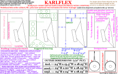
If you build Karlflex with a traditional exponential cut (for dispersion),
plan some way you can remove those wings. Cause looks impossible
to install your driver into that design from any vantage but the front.
-------
I went bottom access non-removable in my above plan. Cause all my
removable wing experiences have been want for some extra bracing
that just wasn't practical. Figure all bracing should have function, and
all function should provide bracing. Only two small panels in mine
(serve as bracing only) fail to meet the dual purpose criteria.
That is a good idea, and a good point .... With some drivers that have the rising upper-mid response a traditional K-slot cut aperture shape makes good sense, but bracing on removable wings is a pain, so making the bottom panel removable is a logical solution.... Might be a little tight to get around to the upper bolts which hold the driver in (yet no worse than some other designs i have seen) but other than that it sounds like a solid plan, i can see how the style of baffle (in your 3d sketch) can improve the access to the bolts from the bottom due to the angle 🙂 ..
Not saying with any certainty that its even an issue. But right where
proper breathing K slot can usually blow out a candle. I worry a bit,
what obstruction those braces might inadvertently become.
Where i show the brace in the sketch (where the upper portion of the slot would normally be) i actually had aperture shape "E" in mind which has no slot in that area , so it should be fine in that case , but aperture shape "D" would require something different i suppose like two braces set off to the side of the slot or something along those lines ...
At 48" tall, would not expect to need an extra Freddi stub to fake it.
Right, with that size cab it should not be a problem developing a fantastically spacious volume for your front chamber (though it might be helpful to have something like a panel with vent or large duct in the path to define the rear chamber volume from the front chamber volume , the Classic Karlsons , Karlflex , ML-Transflex, Brian Steele's POC#2, Karlsonator , Xki , and even the classic helmholtz based series-tuned 6th order bandpass all have this feature)
The Freddi-mod cavity (stub) serves two purposes, it was something Freddi suggested and i originally intended to use it to tame some upper pipe harmonics (created by the main path) but the Freddi-mod also had the added benefit of increasing the front chamber volume which the Karlflex really benefits from ...
Fig666? I am intrigued
Overstuffed, I meant jam a SigmaPro18A2 into a 1955RE-K15.
Proved it can be done, heard result, don't recommend it.
Wasn't speaking of stuffing, the fluffy kind.
---
Wasn't suggesting your internal Litres incorrectly computed.
Just giving the outside figure you could compare to 377.5L
Kenpeter,
Ahhh , ok .... hehe , i misunderstood on both accounts ...
So "overstuffed" as in the SigmaPro18a2 really wants and needs a larger cab right? The VAS figure on that driver is almost 450L eeek ! 😱 ...Suspension is too loose.. Not good .... The k15 surely wants a tighter/stronger or smaller driver ...
I have no clue if my drawing is properly tuned or has even
the slightest practical merit. Its just a drawing, noodling,
daydreaming. You should see the Kuckoo clock fig666...
Your drawing could be worked out in Akabak and adjustments made or features added to get it dialed in.. Akabak is some very powerful and flexible software, although i have to admit that modeling the K-slot is some tricky business.. I am also almost entirely convinced that Akabak did not predict all of the effects provided by the front chamber in this series tuned sort of of arrangement, but Akabak will still get you close enough to build a good test box...
Now what on earth is "Kuckoo clock fig666"?
Last edited:
Silly plan to focus the upper chamber action to a vertical stripe
directly behind the slot and bounce the echos out in the fewest
possible passes. Alternative to lossy damping with stuffing.
Karlson had drawn a "Fig 6", ask Freddi. But its curved panel
focus is a horizontal stripe. Makes no sense how this is going
to exit a vertical slot. John's drawing is just whack. I fixed...
Not transflex or simple or a subwoofer, doesn't belong here.
Crosley chamber / Kuckoo clock / Fig 666 / Go figure...
Attachments


Last edited:
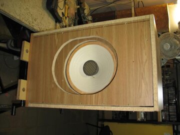
This bird flies best without flapping it's wings
Sebastian,
Thank you😀 That was the idea, to sum up the simple version and release an official sketch/plans for it ..
and yes, a small amount of added texture when appropriate, it is a tasteful coloration, subtle and musical (at least it is the case with this Karlflex12)... Sounds more lively than a common direct radiating box speaker...
Like Freddi says it is best to use some bracing to stabilize the panels and wings .... Even with our aperture style "E" it is still a good idea to use a brace... Panel flex just results in loss and an undesirable form of coloration ...
The aperture/front chamber area is a low pressure area at the box fundamental but can become a high pressure area at higher frequencies (such as harmonics or around the front chamber's resonant range)
Nice sum up, of your impressive work
What you discripe about the Karlflex sound is very interestingly. This vibrant resonance sound will definitely set it apart from the ordinary home box speaker, which I often think sounds a sort of dry, lacking texture and livelyness, in short unmusical.
Sebastian,
Thank you😀 That was the idea, to sum up the simple version and release an official sketch/plans for it ..
and yes, a small amount of added texture when appropriate, it is a tasteful coloration, subtle and musical (at least it is the case with this Karlflex12)... Sounds more lively than a common direct radiating box speaker...
So about the front aperture, would it be counterproductive to bracing it to much, making it to rigid?
Like Freddi says it is best to use some bracing to stabilize the panels and wings .... Even with our aperture style "E" it is still a good idea to use a brace... Panel flex just results in loss and an undesirable form of coloration ...
The aperture/front chamber area is a low pressure area at the box fundamental but can become a high pressure area at higher frequencies (such as harmonics or around the front chamber's resonant range)
Last edited:
Like Freddi says it is best to use some bracing to stabilize the panels and wings .... Even with our aperture style "E" it is still a good idea to use a brace... Panel flex just results in loss and an undesirable form of coloration ...
The aperture/front chamber area is a low pressure area at the box fundamental but can become a high pressure area at higher frequencies (such as harmonics or around the front chamber's resonant range)
Ok I see. My plan is to use some screws, as bracing, through the apature and into the frontplate (driver plate).
Fig.6 was Karlson's reasoning using ray tracing thinking this or in conjunction with Fig.8's sidewall curved surfaces would get more overall energy out the aperture
without Akabak - for a regular K, how might one estimate the needed/optimal size of the front chamber as not to waste overall bulk?
- are WinISD bandpass sims close enough?
Lafayette Eliptoflex - RJ speaker without a dispersion lens
- the "lip" part were raised ridges at the front perimeter of the speaker baffle's cutout
without Akabak - for a regular K, how might one estimate the needed/optimal size of the front chamber as not to waste overall bulk?
- are WinISD bandpass sims close enough?
An externally hosted image should be here but it was not working when we last tested it.
Lafayette Eliptoflex - RJ speaker without a dispersion lens
An externally hosted image should be here but it was not working when we last tested it.
Russian diy Eliptoflex sans "lips"- the "lip" part were raised ridges at the front perimeter of the speaker baffle's cutout
Last edited:
post 1611 is a marvelous, succinct (detailed graphic) and auspicious point in the thread so far 😀😀 - - ( Kenpeter's K-variant is cool)
Is it only me, or the attached diagrams in that post are only in size of thumbnail?
Won't be enlarged when clicked🙁
"Is it only me, or the attached diagrams in that post are only in size of thumbnail?"
I see two graphs, no images.
I see two graphs, no images.

Freddy: I like the look of the tapers in this new design. Have you tried both profiles and which do you prefer and why? Thanks Moray James.
PS: you may recall that I used a horn of plenty style profile where I had the tapers go horizontal just at the top of the driver and I felt that did away with most all the echo effect they can make. I like this even more because it keep air load over more of the woofer than what I was doing yet it achieves the same results I expect.
PS: you may recall that I used a horn of plenty style profile where I had the tapers go horizontal just at the top of the driver and I felt that did away with most all the echo effect they can make. I like this even more because it keep air load over more of the woofer than what I was doing yet it achieves the same results I expect.
CLS and DJK or anyone else who cannot see the Karlflex file, this may help
and
I am using Mozilla Firefox and it views alright for me, but it is possible that my image host service that i used isn't compatible with every browser or might not be available in some parts of the world ...
I zipped up some files for the Karlflex to a zip file and uploaded it to "zeta-uploader" you can download it until it becomes unavailable (in four or five days) .....
I also attached the main full size sketch (from #1611) using DIYaudio's file hosting, it may work better for some ...
https://www.zeta-uploader.com/806379589
"Is it only me, or the attached diagrams in that post are only in size of thumbnail?"
I see two graphs, no images.
and
Is it only me, or the attached diagrams in that post are only in size of thumbnail?
Won't be enlarged when clicked🙁
I am using Mozilla Firefox and it views alright for me, but it is possible that my image host service that i used isn't compatible with every browser or might not be available in some parts of the world ...
I zipped up some files for the Karlflex to a zip file and uploaded it to "zeta-uploader" you can download it until it becomes unavailable (in four or five days) .....
I also attached the main full size sketch (from #1611) using DIYaudio's file hosting, it may work better for some ...
https://www.zeta-uploader.com/806379589
Attachments
Last edited:
Thanks a lot. Now I got it big and clear.
I use Chrome, the thumbnails in the previous MMJ's post move a little when being clicked, but stay at the same small size.
In freddi's post # 1631, the diagram is enlarged when clicked, and can be enlarged further by the 4-arrow icon at the low-left corner.
I use Chrome, the thumbnails in the previous MMJ's post move a little when being clicked, but stay at the same small size.
In freddi's post # 1631, the diagram is enlarged when clicked, and can be enlarged further by the 4-arrow icon at the low-left corner.
Thanks a lot. Now I got it big and clear.
I use Chrome, the thumbnails in the previous MMJ's post move a little when being clicked, but stay at the same small size.
In freddi's post # 1631, the diagram is enlarged when clicked, and can be enlarged further by the 4-arrow icon at the low-left corner.
Awesome! Ok, glad it worked, hopefully everyone can see it now in one post or another 🙂
Figure 666
Kenpeter,
Thank you for posting the Kuckoo clock figure 666... What a fun variant , and still retains so many of the classic Karlson features... The big internal panel with the 4 holes is what divides the front chamber from the back chamber on the Kuckoo , the front:back ratio also looks to be along the lines of what the classic K-boxes used🙂 (instead of an undersized front chamber like the Karlflex uses)....... The panel/brace just above the driver in the back chamber forms "low pass choke" (as it was referred to in some of the K diagrams posted by Freddi, or other drawings i have seen around) , but could also be said to form a compression chamber .......................... Then there is also the K-slot wing brace that doubles as mass loading just above the driver in the front chamber ..... If these extra mass loading & choke/duct features are truly acoustically relevant (each with it's own corresponding useful resonance/purpose) then it would make this box more than just a 6th order design, possibly 8th order, or even 10th order because we get 2 additional orders for every chamber & vent set if everything is actually acoustically functional ....
I have on a few occasions tried adding the "low pass choke" (small vented rear compression chamber) feature to some of my Akabak scripts but so far i have not had any luck seeing that particular constriction do anything positive for my simulations, so i am either doing it wrong, or i have to think that Akabak doesn't predict all of the benefits of that feature properly or perhaps it just doesn't really do much of anything for you and simply happened to be a convenient place to put a brace in the old K-cabs *shrug* 😛 ....
On the other hand that brace holding the K-wings steady which also doubles as a Mass Loading duct is interesting and gives me an idea about using something like it as a second ML-vent in a series of three chambers & two vents (plus a third if you consider the mouth a vent) in some form of a modified Tapped Pipe or ML-Transflex sort of cabinet, i might try dabbling with that idea a little bit in order to make an 8th order series-tuned variant of the ML-Transflex (or maybe some sort of 8th order Karlflex) ......
I can draw a sketch if anyone wants to see but of course determining whether or not it can be made to work in Akabak will let me know if it is an arrangement worth pursuing ...
Silly plan to focus the upper chamber action to a vertical stripe
directly behind the slot and bounce the echos out in the fewest
possible passes. Alternative to lossy damping with stuffing.
Karlson had drawn a "Fig 6", ask Freddi. But its curved panel
focus is a horizontal stripe. Makes no sense how this is going
to exit a vertical slot. John's drawing is just whack. I fixed...
Not transflex or simple or a subwoofer, doesn't belong here.
Crosley chamber / Kuckoo clock / Fig 666 / Go figure...
Kenpeter,
Thank you for posting the Kuckoo clock figure 666... What a fun variant , and still retains so many of the classic Karlson features... The big internal panel with the 4 holes is what divides the front chamber from the back chamber on the Kuckoo , the front:back ratio also looks to be along the lines of what the classic K-boxes used🙂 (instead of an undersized front chamber like the Karlflex uses)....... The panel/brace just above the driver in the back chamber forms "low pass choke" (as it was referred to in some of the K diagrams posted by Freddi, or other drawings i have seen around) , but could also be said to form a compression chamber .......................... Then there is also the K-slot wing brace that doubles as mass loading just above the driver in the front chamber ..... If these extra mass loading & choke/duct features are truly acoustically relevant (each with it's own corresponding useful resonance/purpose) then it would make this box more than just a 6th order design, possibly 8th order, or even 10th order because we get 2 additional orders for every chamber & vent set if everything is actually acoustically functional ....
I have on a few occasions tried adding the "low pass choke" (small vented rear compression chamber) feature to some of my Akabak scripts but so far i have not had any luck seeing that particular constriction do anything positive for my simulations, so i am either doing it wrong, or i have to think that Akabak doesn't predict all of the benefits of that feature properly or perhaps it just doesn't really do much of anything for you and simply happened to be a convenient place to put a brace in the old K-cabs *shrug* 😛 ....
On the other hand that brace holding the K-wings steady which also doubles as a Mass Loading duct is interesting and gives me an idea
about using something like it as a second ML-vent in a series of three chambers & two vents (plus a third if you consider the mouth a vent) in some form of a modified Tapped Pipe or ML-Transflex sort of cabinet, i might try dabbling with that idea a little bit in order to make an 8th order series-tuned variant of the ML-Transflex (or maybe some sort of 8th order Karlflex) ......I can draw a sketch if anyone wants to see but of course determining whether or not it can be made to work in Akabak will let me know if it is an arrangement worth pursuing ...
fwiw I think the rear lowpass shelf when added to Acoustic Controll's 115BK, in the form of KK-Audio's interpretation of the same basic cabinet, made response and Z curve a bit rougher. The front shelf seems to help K15 (I think) - the rear shelf could be useful in tuning system Q (subjectively by listening to slapped upright bass, drums) - a brace on the back panel on a K15 size coupler without a rear shelf introduced a new mild dip.
here's the small signal impedance effect of moving the choke bar on the 1954 K12
KK-Audio added a rear shelf right above the woofer - otherwise it was pretty much like the 115K below
other than an extra reflector panel
here's the small signal impedance effect of moving the choke bar on the 1954 K12
An externally hosted image should be here but it was not working when we last tested it.
An externally hosted image should be here but it was not working when we last tested it.
KK-Audio added a rear shelf right above the woofer - otherwise it was pretty much like the 115K below
other than an extra reflector panel
An externally hosted image should be here but it was not working when we last tested it.
Last edited:
fwiw I think the rear lowpass shelf when added to Acoustic Controll's 115BK, in the form of KK-Audio's interpretation of the same basic cabinet, made response and Z curve a bit rougher. The front shelf seems to help K15 (I think) - the rear shelf could be useful in tuning system Q (subjectively by listening to slapped upright bass, drums) - a brace on the back panel on a K15 size coupler without a rear shelf introduced a new mild dip.
here's the small signal impedance effect of moving the choke bar on the 1954 K12
An externally hosted image should be here but it was not working when we last tested it.
KK-Audio added a rear shelf right above the woofer - otherwise it was pretty much like the 115K below
other than an extra reflector panel
An externally hosted image should be here but it was not working when we last tested it.
Freddi ,On the WT3 impedance plot of the 1954 K12 it looks like the addition of the "choke" (which i think is a constriction creating small vented compression chamber in most of the diagrams i have seen) develops an extra resonance up high around 230hz in this case, and that is what causes the impedance dip there ... That added loading in the midbass could damp the cone and help to tighten up the sound of that range (was there a bump or a dip seen in the frequency/amplitude response of that box around 230hz?) ...
About the 115BK: Three chambers and three vents/ducts (if you count the mouth or K-slot as a vent) all in series was a common configuration for a K-box right? Seems like i have seen it a lot ..... Some even go further to add that shelf in the front, you said it helped the K15 , has anyone been able to measure the difference that the front shelf makes? I am curious to know the effect that it has ..
Freddi , i plan on making one of those Transylvania Power Company style slotted tubes for the Selenium compression driver sometime over the next week , i will get pictures and measurements for you .... I suspect it will need several decibels of padding if used with a Karlflex12 because the D220Ti is a hot driver.
Last edited:
all I have for a front shelf graph is one from a mic on the ground perspective and the coupler probably wasn't as good/smooth as the standard K15 - its a tradeoff from this viewpoint - in K15 it and the rear shelf help tune the 40sq.in. vent a big lower
it'll be interesting for your take on a K-tube vs the Frankenpiezo
- don't know if I've a graph anymore of the Karlsonette
it'll be interesting for your take on a K-tube vs the Frankenpiezo
- don't know if I've a graph anymore of the Karlsonette
An externally hosted image should be here but it was not working when we last tested it.
Last edited:
- Home
- Loudspeakers
- Subwoofers
- New sub design? Constricted Transflex, simple build (series tuned 6th order)