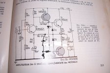
I did a similar power supply during the layout, I did not return to the unipolar circuit, as it was more elegant. Modern 15-25 Amp transistors can be protected with a conventional fuse and at the same time get rid of speaker protection circuits. In the 70s, the analysis and measurement tools available now were not often used, and Google was just a good library with manual search, hence the RCA reference.It is from a RCA application note.
It is a rather regular quasi amplifier, except for the unusual overload protection based on the 4.7V zener, and the singleton-based input, despite the symetrical supplies
It turned out faster 🙂 Yes, thank you, I understand your idea. At high levels, it seems that you need to additionally edit these sources. Now it is easier to consider the forest of harmonics. 🙂. And edit. Although in general for a 5-transistor amplifier, this is very, very good, TND 0.0082% at 8V amplitude. Moreover, at 8 ohms it will be twice as good as 0.0037%. I'm thinking of collecting for myself. Everything for this is already ready , except the amplifier itself . I don't know your name. Very grateful. That was a problem.
Please don't take this the wrong way but you ltspice directive for your distortion analysis looks off. pm me and I'll send you an example to improve the results.
Your rising noise floor is also an issue. You need to short out long time constant caps for the simulation or only start the simulation after the caps are charged. In other words drop cycles until they are charged. You can also use the initial value directive to set components to there charged state.
Good afternoon, stuartmp. I did not find how to contact the personal account through the interface. Can you tell me how to do it?
Last edited:
Click on my name then click on start conversion. This will allow you to personally message meGood afternoon, stuartmp. I did not find how to contact the personal account through the interface. Can you tell me how to do it?
I did a similar power supply during the layout, I did not return to the unipolar circuit, as it was more elegant. Modern 15-25 Amp transistors can be protected with a conventional fuse and at the same time get rid of speaker protection circuits. In the 70s, the analysis and measurement tools available now were not often used, and Google was just a good library with manual search, hence the RCA reference.
You are living dangerously: try to compare the fusing time curves of ultra-fast fuses and the SOA of bipolar transistors, and you will realize that there is a mismatch. In addition, BJT's don't have a spec regarding I²*time for fusing, unlike diodes or thyristors which have a "plasma" type of conduction, and that's for a good reason: there is no safe limit for this parameter.
That said, you can be lucky, and many BJT's vastly exceed their specified SOA, and with the wiring resistance, you might have a lucky escape -but don't count on it-
Even a simple current limiter will often exceed the SOA limit: ideally you need more elaborate circuits, but it is a good starting point, especially for a circuit designed in the early seventies.
Fuses have their issues too: they introduce thermal distortion, and if you try to include them in the feedback loop, problems can show when the fuse blows and the amp operates in open loop
The fuses worked fine for protection in the era of RCA hometaxial transistors. Not with modern stuff.
There is no problem at all to put a resistor in the emitter, I just noted that the power decreases quite significantly, with its small total value. It all depends on the supply voltage. I also modeled this circuit on 36 V 20W , with two pairs of output transistors and of course 0.2 Ohm resistors. The parameters of the circuit at the same time at 8 ohms of load remain the same high.
Nelson Pass considers a little bit of dc through speakers benefficial for overall distortion pattern.
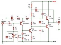
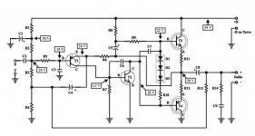
Schemes from France,
Japan, Russia, Brazil.
Japan, Russia, Brazil.
Attachments

Last edited:

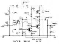
Those old simple Singleton amps is my favorite Solid State ones , they usually sounds much better to my ears than those amps with differential pair at input ,
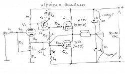
btw , I developed one AB class hibrid amp based on that Singleton concept , intern is DC coupled , with one small Triode at input , one BJT as VAS , and standard lateral power FET pair OPS, PSU is unipolar with artificial ground point.
THD @ 1W/8 Ohm ~ 0,007%
btw , I developed one AB class hibrid amp based on that Singleton concept , intern is DC coupled , with one small Triode at input , one BJT as VAS , and standard lateral power FET pair OPS, PSU is unipolar with artificial ground point.
THD @ 1W/8 Ohm ~ 0,007%
Attachments
That’s a good idea. It overcomes the two basic limitations of the original circuit. The limited current gain of the outputs (with typical bipolars), and the problems with second breakdown that can arise when using transistors that can overcome the gain problem. Then you are free to crank the supply voltage. In the original configuration, practical limitation is 30 or maybe 40 volts.
Just using MJL21194 or C4281 outputs isn’t a panacea. Gain really isn’t high enough, and it falls off fast at low Vce. Something like D44/45 works better - but don’t even try running those over 40 volts. VAS/driver types as outputs are also tempting - but many of those have gain that falls like a stone below 5 or 10 volts. And cranking the Vcc up still might not be an option. Mosfets do solve that - you just lose that bit of swing due to Vth but you can up the Vcc to compensate without danger.
Just using MJL21194 or C4281 outputs isn’t a panacea. Gain really isn’t high enough, and it falls off fast at low Vce. Something like D44/45 works better - but don’t even try running those over 40 volts. VAS/driver types as outputs are also tempting - but many of those have gain that falls like a stone below 5 or 10 volts. And cranking the Vcc up still might not be an option. Mosfets do solve that - you just lose that bit of swing due to Vth but you can up the Vcc to compensate without danger.
- Home
- Amplifiers
- Solid State
- New simple amplifier