In your Elvee collection, there was even an analogue, a little overcomplicated, but there is. What do they write about him interestingly ?

#21 I have a BEAG amplifier from the 70s. It is assembled according to this scheme on 2N3055. 50W \ channel. The sound is pleasant🙂
Last edited:
Post 21 seems to be an amplifier sold by WEM a music / PA amp sold in the UK in the 70's here in the uk the schematic I believe was an original RCA design Sounded ok
Again the original start to this do not believe the SIM results you have no chance of getting these low distortion results in the real world
Again the original start to this do not believe the SIM results you have no chance of getting these low distortion results in the real world
#21 I have a BEAG amplifier from the 70s. It is assembled according to this scheme on 2N3055. 50W \ channel. The sound is pleasant🙂
In my old version of LTspice, there were no simpler complementary pairs. And the update doesn't work for her. Some kind of problem.


It seems to me that in the 70s, in this scheme, all attention was paid to the power of 70W and the presence of protection, which was relevant for rock concerts. I think then they underestimated the possible potential . They wanted more and louder, 5-25 kilowatts. 🙂 And with the simulator, the opposite situation may well turn out to be. 50/50.Post 21 seems to be an amplifier sold by WEM a music / PA amp sold in the UK in the 70's here in the uk the schematic I believe was an original RCA design Sounded ok
Again the original start to this do not believe the SIM results you have no chance of getting these low distortion results in the real world
I compared, the capabilities of JLH are not a competitor to this scheme.Figure 5 - JLH(mod) amplifier.
#21 http://rt22.ru/viewtopic.php?f=52&t=1627
Dual? Philips? Grundig?
There are options with a combination of BJT\ Mosfet at the output 🙂
Dual? Philips? Grundig?
There are options with a combination of BJT\ Mosfet at the output 🙂
Attachments
Last edited:
More than 10 mA DC current through the speaker.The picture in post 18 has the "magic bootstrap"
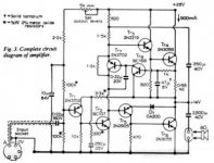
Output cap C5 in post 18 has double use as bootstrap cap .. and yes, there is a small offset current of 20 mA.
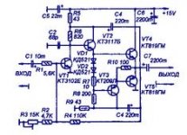
Yes C6 in the second schematic is very important.A 10uF cap in parallel with each diode in a symmetrical drive does wonders.Figure 5 - JLH(mod) amplifier.
You can try a germanium amplifier based on a similar schematic and you won't be dissapointed.One mention where the author is slightly wrong: the 22 ohms biasing resistor should better be an NTC one.
No crossover distortion and perfect linearity to 100khz!
Lots of germanium trz in old stocks in Russia too like p214/p215 😉
No crossover distortion and perfect linearity to 100khz!
Lots of germanium trz in old stocks in Russia too like p214/p215 😉
The JLH circuit has some serious problems but yours has the following issues:
1. 2SC542P is a 1 Watt transistor (TC=25) and your idle dissipation is about 8 Watts. Add to that the peak power of ~5V^2/4 Ohms = 6.5 Watts. If you have a fair heat sink, you need a transistor that is good of 2x the TC=25 dissipation spec, ie you need a 30-Watt+ transistor. For amps operating at similar voltage, a TO-220 is suitable. But few such transistors have the gain to operate without a driver. You need a gain of 100 at 2.4 Amps.
2. Without emitter resistors, even larger transistors would soon thermal runaway.
3. Two diodes is a crude bias with no adjustment requiring large emitter resistors or a very class-A bias. A VBE multiplier is best but you could use one diode and a resistor (about 15 Ohms) if being simple is important. LV's auto bias is a great fit for small amps like this and may make emitter resistors unnecessary.
4. Moving from the single input transistor to a LTP (two transistors) allows you to deal with the capacitor issue, without resorting to a trim-pot offset adjustment.
I am not fond of circuits that run more than 50mA idle current, but that means getting an impressive THD is difficult.
Almost any point of the above can be easily challenged. There are a lot of ways to complicate the scheme, and very few that can make it easier. In LTspice transistors are immortal, without brakes invented by someone. 🙂The JLH circuit has some serious problems but yours has the following issues:
1. 2SC542P is a 1 Watt transistor (TC=25) and your idle dissipation is about 8 Watts. Add to that the peak power of ~5V^2/4 Ohms = 6.5 Watts. If you have a fair heat sink, you need a transistor that is good of 2x the TC=25 dissipation spec, ie you need a 30-Watt+ transistor. For amps operating at similar voltage, a TO-220 is suitable. But few such transistors have the gain to operate without a driver. You need a gain of 100 at 2.4 Amps.
2. Without emitter resistors, even larger transistors would soon thermal runaway.
3. Two diodes is a crude bias with no adjustment requiring large emitter resistors or a very class-A bias. A VBE multiplier is best but you could use one diode and a resistor (about 15 Ohms) if being simple is important. LV's auto bias is a great fit for small amps like this and may make emitter resistors unnecessary.
4. Moving from the single input transistor to a LTP (two transistors) allows you to deal with the capacitor issue, without resorting to a trim-pot offset adjustment.
I am not fond of circuits that run more than 50mA idle current, but that means getting an impressive THD is difficult.
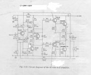
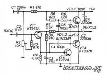
It is from a RCA application note.In your Elvee collection, there was even an analogue, a little overcomplicated, but there is. What do they write about him interestingly ?
View attachment 1099189
It is a rather regular quasi amplifier, except for the unusual overload protection based on the 4.7V zener, and the singleton-based input, despite the symetrical supplies
- Home
- Amplifiers
- Solid State
- New simple amplifier