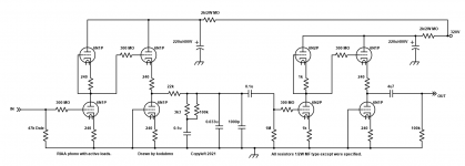
So I designed a circuit board for MM and high output MC carts.
It uses active loading, and 16 triodes.
9AJ base. I designed it for 6N1P 1st and 2nd position, 6N2P for 3rd, and 6N1P for 4th. You can sub 6DJ8 for the 6N1P in this design, too. Any tubes that fit and have a 9AJ pinout will work if you make the appropriate resistor changes.
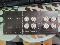
Here's an example I built as a test. The board requires 12V for heat (DC preferred, no special accommodation was made for AC so some hum might ensue) and 280V or so for B+.
I'm selling the blank boards for 25$ plus post. I can also include parts if you need them.
I'm offering this complete board including new tubes for 150$ shipped to you. All the film capacitors are metallized polypropylene, and the sockets are ceramic.
If you're interested in any of this, send a message!
Have an awesome day!
It uses active loading, and 16 triodes.
9AJ base. I designed it for 6N1P 1st and 2nd position, 6N2P for 3rd, and 6N1P for 4th. You can sub 6DJ8 for the 6N1P in this design, too. Any tubes that fit and have a 9AJ pinout will work if you make the appropriate resistor changes.
Here's an example I built as a test. The board requires 12V for heat (DC preferred, no special accommodation was made for AC so some hum might ensue) and 280V or so for B+.
I'm selling the blank boards for 25$ plus post. I can also include parts if you need them.
I'm offering this complete board including new tubes for 150$ shipped to you. All the film capacitors are metallized polypropylene, and the sockets are ceramic.
If you're interested in any of this, send a message!
Have an awesome day!
Attachments

Last edited:
Is that grid stopper 300 meg ohm? That would definitely roll off the highs.
Nice design
Nice design
Last edited:
What do you mean? Schematic is in post one complete with RIAA network.
I know, but I mean the measured RIAA characteristic when the PCB is populated with the components.
No. I lack the equipment for that kind of testing. My ears and the math say it's good though.
If you have the equipment I could send a board to test.
If you have the equipment I could send a board to test.
Nice design and layout.
I have lots of 6N1Ps and 6N2Ps so I might be interested if there is going to be boards available.
I have lots of 6N1Ps and 6N2Ps so I might be interested if there is going to be boards available.
Any chance to publish the actual RIAA characteristic? 🙂
If you use crap parts you would have crap results, of course.
Using good commercial parts of values as noted, the accuracy is OK. Better than OK. Very-very good. Within 0.026dB of the prescribed time constants.
I have assumed that a cathode follower is 500 Ohms out, a grid is infinite, and the tubes are flat over the audio band (no 300Meg gridstopper).
Attachments
No. I lack the equipment for that kind of testing. My ears and the math say it's good though.
If you have the equipment I could send a board to test.
OK kodamix, I was asking this because I am perhaps buying a board.
Will see if lowering the supply voltage to 250V will also give good results when analyzing your design will LTspice.
Joe.
- Home
- Amplifiers
- Tubes / Valves
- New PCB for MM RIAA using 9AJ based 9 pin tubes.