How critical are the size/type of the caps?
For example, is there any problem if the 22uF to Gnd on the input IC (opa627) is actually 47uF or maybe a film capacitor? Same thing about the two 22uF caps on the 4N35?
On one circuit I see the 22uF/100 MKS4 caps specified for all 3 of these.
Also, i see the 0.1uF cap on the 4N35 opto specified as the 630v Zn 3% (the Phillips cap) - is there similar optional devices and for what advantages? Musicaps? Obbligato? Mundorf? Rifa Styrene? etc
You could reduce the center 10K divider resistors. What output transistors?
2sk2013 and 2sj313
Resistors R11 and R30 exactly 100 ohms?
Diod 4N35: forvard input - 1.2V, 10mA.
at 10 mA across the resistor the voltage will be 100*0,01=1V.
1,2V Optocoupler + 1V resistor = 2.2V
quiescent current 2.2/(10+10)= 110 mA
Where was I wrong?
Diod 4N35: forvard input - 1.2V, 10mA.
at 10 mA across the resistor the voltage will be 100*0,01=1V.
1,2V Optocoupler + 1V resistor = 2.2V
quiescent current 2.2/(10+10)= 110 mA
Where was I wrong?
I trust your measurements it sound like the 4N35 is saturating. I measure no higher than .16 volts across the 100 Ohm on 4 units. You can reduce R28 and R33, R15 and R23. Try 1.5 - 2.2 K
An error was found when connecting the optocoupler transistor. After the fix, everything worked as it should.
I apologize for my negligence and your time spent.
I apologize for my negligence and your time spent.
Hello everyone .
I have completed the amplifier, but it is not silent, I hear a buzz from the headphones, the buzzing increases by turning the volume knob. Partially delimits the buzz by connecting the gnd out with the ground.
What can it be?
I have completed the amplifier, but it is not silent, I hear a buzz from the headphones, the buzzing increases by turning the volume knob. Partially delimits the buzz by connecting the gnd out with the ground.
What can it be?
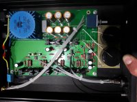
Please post well-lit, in-focus photos of your build. 😀
Try removing C2 and C7, the 100pF capacitors in the feedback loop
Try removing C2 and C7, the 100pF capacitors in the feedback loop
In my (just completed) build, it was buzzing until I fully closed the box. I guess the buzz depends on the volume control, as the pot affects the impedance between the opamp noninverting input, the ground, and the signal source. In any case it went quiet with the box (a Hammond extrusion) closed and sealed.
I had a similar issue previously with my build of Pearl 2 (thank you Wayne 🙂 ), and also could only solve it by fully closing the box. There I had to use lock washers under some of the flat head screws to get electrical contact between anodized panels of the enclosure.
I had a similar issue previously with my build of Pearl 2 (thank you Wayne 🙂 ), and also could only solve it by fully closing the box. There I had to use lock washers under some of the flat head screws to get electrical contact between anodized panels of the enclosure.
Last edited:
Listening to music through the amplifier for a few days. Very pleased with the sound.
Plays better than my Lehmann clone with feedback, and it is very good.
On input cap Epcos 1uF 630V, opamp OPA2134.
Thanks for this great scheme!

Plays better than my Lehmann clone with feedback, and it is very good.
On input cap Epcos 1uF 630V, opamp OPA2134.
Thanks for this great scheme!
Last edited:
Fabulous. I'm really looking forward to building and hearing one.Once the final changes are made it will be available in the diyAudio store.
Problem solved guys, it was a noisy led, I eliminated the leds and cap, and I jumpered r9 r13, now everything is perfect 🙂
Once the final changes are made it will be available in the diyAudio store.
Will these be huge changes compared to the first boards Wayne sold. Will your build be based on the new board. Still populating mine one resistor at a time unless the wife says otherwise.
- Home
- Amplifiers
- Pass Labs
- New PassDIY Headphone Amp (now available)