Sorry, Vincent!
I told about main case for, IMO, real filtering +U, acc. my moto "Hi-END is back proportional to the number of composite parts" 🙂 For ex.: In ampl. track of SE passive parts must be no more 5-6, but with more than good quality and not for 20 cents every....🙂
I told about main case for, IMO, real filtering +U, acc. my moto "Hi-END is back proportional to the number of composite parts" 🙂 For ex.: In ampl. track of SE passive parts must be no more 5-6, but with more than good quality and not for 20 cents every....🙂
cgraf, What is the purpose of TRA?
It appears to me that it does nothing but set the current through the two diodes, and without an additional limit resistor, can be turned down low enough that you will blow the diodes D7 and D8.
It looks like T3 has it's collector and emitter swapped if it is meant to be a current source with R2 ans the current sense resistor.
Indeed. No need for a trimmer there. Replace with one 47K 1W resistor. The transistor is also drawn wrong. See schematic at post #45.
While we're at it, D10 is also the wrong way around.
Since you're not showing the mains side of the transformer: the fuse and the switch must be on the live wire. It doesn't hurt (at the contrary) to use a dpdt to switch both live and neutral.
Since you're not showing the mains side of the transformer: the fuse and the switch must be on the live wire. It doesn't hurt (at the contrary) to use a dpdt to switch both live and neutral.
You don't need a separated heater supply for V2, the 4A SMPS can do both. I have tested it, there is no difference in sound.
You should add a *good quality* bypass capacitor over C2L and C2R, at least 2µ2. (Mundorf Supreme for example)
Adjust R4 for best sound with your headphones.
You should add a *good quality* bypass capacitor over C2L and C2R, at least 2µ2. (Mundorf Supreme for example)
Adjust R4 for best sound with your headphones.
Thanks Vincent
Then I have to open the amp each time I change the headphones, I already have various models with low to high impedance (just joking)
I finished the pcb design (which is kind of stuffed now with the heatsink space and the big caps...) and start now to source the parts...
I think when the amp runs I have to send you and Benoît a bottle of Bordeaux (I cannot send Swiss chocolate to Belgian citizens ) for your help.
Best regards from Geneva
Christoph
Adjust R4 for best sound with your headphones.
Then I have to open the amp each time I change the headphones, I already have various models with low to high impedance
(just joking)I finished the pcb design (which is kind of stuffed now with the heatsink space and the big caps...) and start now to source the parts...
I think when the amp runs I have to send you and Benoît a bottle of Bordeaux (I cannot send Swiss chocolate to Belgian citizens
) for your help.Best regards from Geneva
Christoph
Attachments
Lol. 🙂
Order UF4007 instead of 1N4007, they make less switching noise.
Good luck with your project and don't forget to take pictures.
Order UF4007 instead of 1N4007, they make less switching noise.
Good luck with your project and don't forget to take pictures.
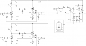
Your 6080s are biased off unless you use a negative voltage supply for the current source. Otherwise you need the grids biased above ground (half way between ground and B+).
Otherwise you need the grids biased above ground (half way between ground and B+).
Easy to do: leave out R7 and C3, replace R1 with 1K multiturn trimmers, and adjust to have 90v at V2 plate.
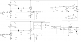
Final Version ?
Updated schematics:
As the opinions differ, I will leave some space on the PCB and will then be able to compare.
Best regards
Christoph
Updated schematics:
leave out R7 and C3, replace R1 with 1K multiturn trimmers, and adjust to have 90v at V2 plate.
As the opinions differ, I will leave some space on the PCB and will then be able to compare.
Best regards
Christoph
Attachments

Last edited:
Your 6080s are biased off unless you use a negative voltage supply for the current source. Otherwise you need the grids biased above ground (half way between ground and B+).
???
According to datasheet's curves, with 100V across the 6080 and 50ma current draw, Vg is -40V and the CCS has thus 40V to operate with the 6080 input referred to ground, which is way more than enough for the voltage swings into headphones.
You can of course bias the tube at 90V but then watch out for dissipation on the ccs (it goes up by 2.5x).
Hi Benoît
Glad you responded. Had the same impression but I am not really that much experienced. Anyway, what I have on the PCB leaves now all flexibility to test several setups which is great.
Best regards
Christoph
Glad you responded. Had the same impression but I am not really that much experienced. Anyway, what I have on the PCB leaves now all flexibility to test several setups which is great.
Best regards
Christoph
Hi,
This circuit whilst adding another 6AS7 should do a much better job at driving cans, any can really.
<snip>
Do you know whitch is the current drwan from 6SN7 SRPP stage and the current drawn from the 6080 output stage ?
Thanks
Ciao,
Francesco
Hi,
This circuit whilst adding another 6AS7 should do a much better job at driving cans, any can really.
<snip>
Hello you guys🙂
I've been following this thread, it's very exciting.. My needs for a headphone amp is growing like my passion for tubes! My phones are a pair of Sennheiser HD570 (64 ohm)
That's why I find this schematic quite exiting, but.. I am no technical enginer or designer of schematic's so I have to feel free and ask: Will this amplifier actually work with my cans or is it a theoretical circuit which requires a lot of adjustments before it can operate?
I have read alot on the Tube Cad Journal about wcf circuit and now my brain is full, and a liiiiiiittle bit confused😛
I really like this circuit and for two channels it will give me four tubes which suits me perfectly for the physical design of my amp.
I hope you good people in the world will help me so I can start collecting parts for this head-amp projekt🙂
Best regards
Henrik
Hi good people🙂
Is there really nobody who can or will answer me in this thread?
fdegrove: How about you, you posted this wcf schematic and it would suits me fine to build an OTL headphone amp out of this circuit😉
I look forward to feedback 🙂
Regards
Vingborg
Is there really nobody who can or will answer me in this thread?
fdegrove: How about you, you posted this wcf schematic and it would suits me fine to build an OTL headphone amp out of this circuit😉
I look forward to feedback 🙂
Regards
Vingborg
Hi,
Cgraf,
What gain are you getting from your headphone design?
BTW I am buying this for my 6.3Vdc heater:
DC DC 4V 32V to 1 2V 32V 12A Step Down Power Apply High Power Good | eBay
Cgraf,
What gain are you getting from your headphone design?
BTW I am buying this for my 6.3Vdc heater:
DC DC 4V 32V to 1 2V 32V 12A Step Down Power Apply High Power Good | eBay
Hi,
This circuit whilst adding another 6AS7 should do a much better job at driving cans, any can really.
An externally hosted image should be here but it was not working when we last tested it.
SRPP input stage followed by a WCF output. Z out should be well below 8 ohm.
You can even do away with the bypass cap of the bottom half of the WCF it's only degrading the sound.
Can you explain why we need SRPP to drive the output follower? Why WCF can't be driven by simple common cathode stage?
Can you explain why we need SRPP to drive the output follower? Why WCF can't be driven by simple common cathode stage?
We can use simple common cathode stage, no need for SRPP. There is no low impedance load which requires SRPP's push pull action. The input stage as shown is not even an SRPP.
- Status
- Not open for further replies.
- Home
- Amplifiers
- Tubes / Valves
- New OTL headphone project with EC88 and 6080