Excellent job.
I tend to stick to known suppliers for my passives and in particular for all active parts.
Even they also do not always get it right. I ordered 4 packets of 5x UF5408 diodes from RS. When I opened the packets, 3 packets was correct, the 4th packet contained 1N5401 diodes, although the part number printed on the packet was correct .😡 But yes, at least they are top quality, no fakes or cheap alternatives.
I can't see why not, but I am sure others will explain why it is not a good idea. 😉 Use an audio taper (log) POT.Can I add a 100k pot at the input and still drive it to full output using say a typical CD player?
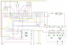
Some asked me for a "wiring diagram". This is how I wired it, using tag board for most of the circuit. Some resistors are mounted directly onto the valve bases. The component positions are almost exactly as the original 5-20. The wire colors are purely to visualize the various connections, it is not according to any wiring color code or standard.
(The input gnd is actually connected to the R1+C12 [1M + 50uF] gnd junction)
I have a high res. image, but it is almost 10MB big.
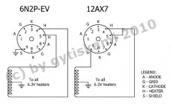
You can also use a 6N2P instead of the 12AX7 / ECC83 (did not compare them yet, so do not know if it is better or not.) They are almost identical, but the heater connections are different. I fitted a switch to easily swap between the 2, like this:
Attachments

Reduce Sensitivity
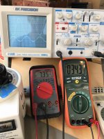
I built the CB 4-30 version and it's way too sensitive. 36mv in is max before distortion. It's configured for variable feedback and as I apply more feedback the gain and sensitivity also increases. I thought more NFB would reduce the gain.
The only difference is I used 5881 tubes and cathode bias 8K transformer. Cathode resister is 470 ohm with 390v on the center tap of the transformer.
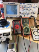
The picture shows the scope the top being the output the bottom showing the NFB the right DVM showing the input the left showing the amp output.
Any ideas or suggestions on how to reduce the sensitivity or fix a NFB issue maybe?
I built the CB 4-30 version and it's way too sensitive. 36mv in is max before distortion. It's configured for variable feedback and as I apply more feedback the gain and sensitivity also increases. I thought more NFB would reduce the gain.
The only difference is I used 5881 tubes and cathode bias 8K transformer. Cathode resister is 470 ohm with 390v on the center tap of the transformer.
The picture shows the scope the top being the output the bottom showing the NFB the right DVM showing the input the left showing the amp output.
Any ideas or suggestions on how to reduce the sensitivity or fix a NFB issue maybe?
Last edited:
What are you adjusting to apply "more" feedback? If you are making the resistance in the feedback loop larger, it will apply less feedback, and vice versa.
The Claus Byrith 4-30 design has an input sensitivity of ~500mV, at 36mV input clipping voltage, there is something not going right in your implementation. I would debug that first.I built the CB 4-30 version and it's way too sensitive. 36mv in is max before distortion. It's configured for variable feedback and as I apply more feedback the gain and sensitivity also increases. I thought more NFB would reduce the gain.
The only difference is I used 5881 tubes and cathode bias 8K transformer. Cathode resister is 470 ohm with 390v on the center tap of the transformer.
The picture shows the scope the top being the output the bottom showing the NFB the right DVM showing the input the left showing the amp output.
Any ideas or suggestions on how to reduce the sensitivity or fix a NFB issue maybe?
I would check the following.
1. Are you sending Positive feedback signal instead of negative feedback.
2. The Design call for getting NFB directly from the 8R speaker connection, are you doing that
3. Are you using Ultra Linear transformer and running in UL mode and not Pentode mode?
The Claus Byrith 4-30 design has an input sensitivity of ~500mV, at 36mV input clipping voltage, there is something not going right in your implementation. I would debug that first.
I would check the following.
1. Are you sending Positive feedback signal instead of negative feedback.
2. The Design call for getting NFB directly from the 8R speaker connection, are you doing that
3. Are you using Ultra Linear transformer and running in UL mode and not Pentode mode?
Yeah I think the input sensitivity might be related to the feedback loop.
Should the feedback be in phase or out of phase with the original signal? Would that be what you mean by Positive feedback or Negative feedback?
I am getting it from the 8 Ohm tap and the the transformer is wired to be UL mode. the Negative of the transformer is tied to ground.
Attachments
I got it. The plus and minus on the output transformer were reversed. I wonder why they were labeled wrong. They were orange and black. the schematic said the orange was the 8 ohm lead.
Swap connection at output stage control grids, not secondary of output transformer.
That's exactly what I was thinking. I'll do that Thanks!
Swap connection at output stage control grids, not secondary of output transformer.
I've seen this advice on a couple of occations without understanding quite why it should make a difference whether primary or secondary side of transformer is revered.
Is there a simple explanation as to why this make a difference.
I've seen this advice on a couple of occations without understanding quite why it should make a difference whether primary or secondary side of transformer is revered.
Is there a simple explanation as to why this make a difference.
There are probably other reasons but for me it was a matter of the color coding on the wire would then be wrong because the black becomes the plus and the orange becomes the minus. If I change it on the primary side the color codes become correct.
I wonder how you would know that in advance before you get it designed and wired. I could also reverse the plate and UL taps should also give me the same result just more wires to change.
I wonder how you would know that in advance before you get it designed and wired. I could also reverse the plate and UL taps should also give me the same result just more wires to change.
You could measure it before cutting the wires and putting it in. You can do that with a scope and a 6V filament transformer. It is easy to swap the primary wires. There are no standards on color there.
I've seen this advice on a couple of occations without understanding quite why it should make a difference whether primary or secondary side of transformer is revered.
Is there a simple explanation as to why this make a difference.
Negative feedback reduces overall gain. When you reverse the phase of the feedback you increase the gain which usually turns your power amplifier into a power oscillator, or at the very least full power from incredibly small input signals.
The way the transformer was wound may result in slightly better overall performance one way than the other. It also gets a bit more complicated when you have asymmetrical taps on the transformer for 4 & 8 ohm loads for example.
I've seen this advice on a couple of occations without understanding quite why it should make a difference whether primary or secondary side of transformer is revered.
Is there a simple explanation as to why this make a difference.
Simple - ish...
If the secondary is a single winding with no taps, then the secondary can be reversed to acheive the same effect. But if the secondary has, for example, a 4 ohm tap and an 8 ohm tap, then reversing the secondary moving the ground from one end to the other will mean that the 4 ohm tap is no longer a 4 ohm tap. The reason is as follows...
The impedance ratio from primary to secondary on a transformer follows the square of the turns ratio. This means that the number of turns between the secondary ground and the 4 ohm tap is greater than the number of turns between the 4 ohm and 8 ohm taps. If the 8 ohm secondary has, for example, 50 turns (an arbitrary number), then its 4 ohm tap would be at around 35 turns (since half of 50 squared is approximately 35 squared).
If the seconday connections are reversed end to end, the 4 ohm tap would then only have 15 turns.
15 squared is 225
50 squared is 2500
2500/225 = 11.11
8 ohms / 11.11 = 0.72 ohms
So the old 4 ohm tap would then be equivalent to a 0.7 ohm tap. That makes no difference if you only use the 8 ohm tap since it still has the same turns ratio with the primary as before. But if you try to use what was previously the 4 ohm tap but which now has 15 turns from the signal ground instead of 35, then the output signal and its corresponding feedback will not be as expected.
Do you see any impacts of using 40% screen grid taps instead of the recomended 33% ? Have you done some modifications to the circuit in order to use the Hammond 1645a ?
I ask this question because I also want to build the CB 4-30. I already have a hammond 1650r wich is also a 5k with 40% screen taps. Having to buy only one opt to build two monoblocks would save me at least 200CAD !
I ask this question because I also want to build the CB 4-30. I already have a hammond 1650r wich is also a 5k with 40% screen taps. Having to buy only one opt to build two monoblocks would save me at least 200CAD !
IMHO, the decision to change from Lundahl to Hammond has more relevant than the difference between 33% to 40% UL tap. That small UL feedback difference should not need initial circuit changes. I would go ahead and save 200CAD.
Do you mean that hammond transformers are that much of a lesser quality ? I was comparing prices between them and edcor opts and hammonds are worth like twice the price for similar specs ! Or is it just a sound difference that’s not really quality related ?
Thanks for your advices !
Thanks for your advices !
Hammond make good transformer. Output Transformer are very subjective. I would finish one mono block. If you like the result, finish the 2nd one and save $200CAD. If you don't decide what you want to change or not then. You can also bread board it first if you care and want a perfect finish look very much.
Last edited:
Hammond make good transformer. Output Transformer are very subjective. I would finish one mono block. If you like the result, finish the 2nd one and save $200CAD. If you don't decide what you want to change or not then. You can also bread board it first if you care and want a perfect finish look very much.
I think I will go the bread board way. It’s almost shure that some tweaks will be needed. It might also help to figure out the best layout to fit my enclosures.
- Status
- Not open for further replies.
- Home
- Amplifiers
- Tubes / Valves
- New Mullard 5-20 (4-30)