Hi,
re answer in post 15. What is the current in the tail (j1+j2)?
The current mirror has the extra Q5 wired in. Does it still split the tail current equally?
The current in Q2 is set by R6 (about 800ua).
What controls the current in q5? With equal source resistors (r4&r5) the mirror action depends on the matching Vbe of q1 &q2 and this would split tail current 50% through r4+q1 and 50%(less a small error) through r5+q2. This all depends on matching source resistors and total tail current EXCEEDING 2 times 800ua.
Please explain where normal mirror theory is modified by your new circuit and what advantage it brings (saying you are "keep the two sides more evenly balanced") but HOW?
Voltage drop is usually around 2V for green and for other colours, except blue which are more like 3-4V.LineSource said:Hi MrEvil,
I would appreciate any Green LED noise and voltage stability information you could share. I want to get educated on:
What is the voltage drop range of Green LEDs?
What is the noise range of Green LEDs?
Which vendor's Green LED has the best voltage stability? the lowest noise?
What are the issues with putting Green LEDs in series in terms of voltage stability and noise? When does a single Zener LED have better specs?
Thanks.
Noise range I cannot comment on since no figures are ever given by the manufacturers, and the only figures I have found are those on this thread in this forum. Looking at it again I see it shows red and orange as lowest noise for low currents, it was the other, not quantitative sources I've read that suggested green, but either way they're definitely lower than Zeners, especially at this voltage range (~6V total).
That thread also explains how noise adds geometrically, so three LEDs in series give less than three times the noise of a single one. Voltage stability with temperature, as a percentage, will remain the same when using multiple LEDs in series. Impedance will increase linearly, so three LEDs will have three times the impedance.
I don't think there is any single best manufacturer. I perused a lot of datasheets and there is a wide variation even from a single manufacturer depending on material used, size and light output (brighter ones tend to behave differently). You need to look at the datasheet to determine which best fits your needs. The ones I chose were made by Vishay. They had the right voltage drop, were quite efficient (better to have more light than heat!) and had reasonable impedance of about 50 ohms (estimated from a graph of I vs Vf), or 150 for all three, compared to about 200 for a single Zener at low current (1mA).
At higher currents and voltages the impedance of Zeners tends to be better. According to that noise thread, Zeners are better for noise at higher voltages.
Tail current is about 2mA total. Tail current is still split equally. The LTP ensures that this is so, with any excess current going down the cascode. Q5 makes no difference to this, since Q2 + Q5 behave as if they were a single transistor. Even if the tail current were too low, the current would still be split evenly since the cascode takes up the slack, it would just unbalance the currents through Q1 and Q2.AndrewT said:Hi,
re answer in post 15. What is the current in the tail (j1+j2)?
The current mirror has the extra Q5 wired in. Does it still split the tail current equally?
The current in Q2 is set by R6 (about 800ua).
What controls the current in q5? With equal source resistors (r4&r5) the mirror action depends on the matching Vbe of q1 &q2 and this would split tail current 50% through r4+q1 and 50%(less a small error) through r5+q2. This all depends on matching source resistors and total tail current EXCEEDING 2 times 800ua.
Please explain where normal mirror theory is modified by your new circuit and what advantage it brings (saying you are "keep the two sides more evenly balanced") but HOW?
The total current through Q2 + Q5 is set by the ratio of R4 to R5. It's somewhat complicated to work out the exact current since it depends on the transistor characteristics, it's easier to simulate it. The current gain here is about 20x, so total current through Q2 + Q5 is 20mA, thus the current through Q5 is that minus the current through Q2 or 19mA in this case.
This means that the current though Q2 is ~1mA, which is the same as the current through Q1. This keeps Q1 and Q2 operating at a more similar point and reduces the difference in temperature between them. Since it is Q1 and Q2 that set the current, this improves linearity. It's not perfectly balanced since Vce of the two is different; for perfectly matched operating conditions an extra cascode transistor could be added (i.e. Wilson current mirror).
Overall it still behaves exactly the same as a normal current mirror, it's just a way of controlling the operating points of the individual transistors.
Hi Mr Evil,
thanks for taking the time to explain that.
I plan to read it a few times till I get my head round it.
Then I'll try and simulate it. I'm still learning to use a sim I downloaded recently.
Thanks again
thanks for taking the time to explain that.
I plan to read it a few times till I get my head round it.
Then I'll try and simulate it. I'm still learning to use a sim I downloaded recently.
Thanks again
Hi Evil! have you any result of simulation? Current mirror? you succeeded in it! Oh! you're so skilled .
thank Evil! current mirrors with single input stage is a difficult thing to me and with symmetrical is a utopian thing
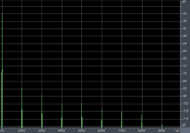
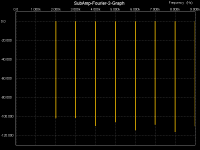
No, I'm limited to 1kHz with my equipment. Given a 6dB/octave decreasing gain I would expect THD to approach 0.1% by 20kHz.MikeB said:Can you also measure thd at 20 khz ?
Mike
Hi Evil
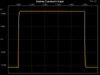
Unless, of course, it's approaching slew then OL THD will be rising very sharply and NFB decreasing.
Cheers,
Greg
Unless, of course, it's approaching slew then OL THD will be rising very sharply and NFB decreasing.
Cheers,
Greg
Yes, there could be (probably is?) a new mechanism at higher frequencies that would increase distortion faster with frequency, but it won't be due to insufficient slew rate, since this amp can provide an adequate 100V/us.amplifierguru said:Hi Evil
Unless, of course, it's approaching slew then OL THD will be rising very sharply and NFB decreasing.
Cheers,
Greg
- Status
- Not open for further replies.
- Home
- Amplifiers
- Solid State
- New mixed-device-type symmetrical folded cascode amp