I fail to see the usefulness of a cardioid response in a narrow band around 700 Hz, with its corresponding hole in the power response.
To me, the biggest advantage of a cardioid is in the midbass, when reflections off the front wall are really a pain. My dipoles at ~60-70 cm off the wall exhibit a nasty cancellation at ~250Hz (which cannot be EQed) and a peak at ~150Hz (which can be EQ-ed) - both the effects of the reflection off the front wall. But above that I don't sense any issues and imaging is as good as it gets.
I also find the claims from SL's site not far off the typical audiophile bollocks. Whatever happened to the man..
"With directivity controlled in this way the LXmini becomes much less sensitive to room placement, while also gaining in 3D imaging precision. The small, full-range driver on top is superbly smooth and detailed. It blends flawlessly with the pistonic, infinite transmission line woofer for a completely neutral sound in a reverberant room"
And how can you feel the subjective transcient & impact of bass without treble ?
Without talking od OB or cardioid patern I 'm saying to myself what is the treble attenuation in this 3" (2"?)? Even a 1" have directivity in the highs...
No reflections feeling because low reflections in this band due to the lacke of treble power ? What a bout the boomy bass when to close to the front & side wall ? Is there a dip hole around 300 hz to allow near walls placement ??? Are the two frequencies extremity cuted to follow some equiliber like the (old) 400 rule ?
This is a major reason I don't post anymore. I simply can not believe that so many in the DIY community continue to follow such misdirection, be it from SL or others. Go back and read the extended arguments SL gave about why the top end needed to be rolled off, about how critical the shape of the equalization curve was, how the correction should be adopted by the recording industry, about what a breakthrough this was. And now it's reduced to "I was correcting for bad recording". It's all too laughable. Not SL. He is a tinkerer and he will continue to be such. No, rather it's those in the DIY community who simple choose not to think for themselves and buy into the nonsense.
Before LCDs went mainstream, the electronics inside the vast majority of CRT based televisions made a loud, continuous ear-piercing squeal at around 16kHz, yet only a very small proportion of people seemed aware of its existence. I learned not to talk about it because others would look at me like as if I was crazy, that's how rare it was being able to hear up to 16kHz. So I can easily forgive disagreements on how things should work in that 10k-20k octave.
~~~
I noticed that SL wants a high damping factor amplifier for that dipole mid-tweeter, yet the full-range cone operates above break-up. After recently re-thinking how speakers work, I now strongly suspect that low damping factor could provide superior performance in that design. In cases where a speaker box is not a factor, it seems to me that a tightly regulated voltage source, combined with a strong motor, could be the worst possible thing for cone resonances. Once the cone breaks up into smaller vibrating masses, an electrically 'clamped' voice coil surely cannot help.
If we think of the cone as a small mechanical transmission line (from voice coil to rubber surround), what we really want is for the voice coil to provide a matched impedance, preferably at all of the relevant frequencies. Mr Linkwitz seems like just the right guy to do some investigating. Perhaps doing tests with series resistors, measuring some impulses and so on.
His recommendation for high-ish damping factor in the amplifiers is not (primarily) for that reason, you understand? His concern is maintaining the designed electrical response so the designed acoustic response yielded is maintained. He's just thinking about consistency of results from various users possibly bringing different combinations of amplifiers together.
That said, in this particular case, the impedance curve of the H1600-04 driver is relatively level throughout the area of usage, so introducing series resistance would still maintain the electrical response but just attenuate it.
Dave.
Last edited:
With just a little more high freaquencies, to hear what could be the subjective perception after the Seas swap : http://www.supravox.fr/mesures/mes135LB1.htm
Is it just to avoid first room resonances in highs that highs are almost cuted after 10 k? ... only high harmonics from the low end should be important ? (Credo is chamber music and classical concert with SL iirc ?! )
Qts is 0.3 instead 0.9 with the Seas... but the Xo is above the OB roll off ? More loss because surround is fabric, very different suspension compliance...
I should really have subjectives testimonies of Orion listeners vs LX Mini vs Pluto ! In same room or not...
This story of missing highs remind me an old "empiric theory" readed in La revue de l'Audiophile french review by Hiraga about the band wide in relation to the Xo of highs with the Xo of low end ! To be short the more bass, the more treble you need and vice versa to have a well-balanced speaker for the ears.
Sorry no direct reference or links ! It is just scheming for a noob like I am to saw so much people get nerves about the best tweeters units : Magnepan, Raal, Tad, JBL, Gotto and see one day such a speaker !
Why not, old German tubes radio and some TV even new are sometimes surprising and more confortable to listen to... Since the 80s digital, Sound quality is focused on details perception and analytic...in the same time subjective experiments maid at BBC shows we don't like it too much in the highs !
Is the age of the ears of the designer can matter here (with all due of respect, it's not a critic) ? Is it psychoacoustic ? Brain reconstruct some missing highs harmonics by memory of old listened sounds (instruments are well identified for a classical music enthusiast !)... I would like to understand more, does him paper seem clear enough for you ?
Last edited:
High damping factor? How high? It's been shown many time by many people that once you get a damping factor above about 10 it has little impact on the system response. Anything over 25 is more than enough. Additionally, the roll of electrical damping is only significant around an octave to each side of the driver resonance. Above that and it all drive mass that dominates. Below it compliance.
I also agree with the comment by bzfcocon. Having the cardioid transition at 700 Hz really makes no sense. It's in the transition region between the sparsely populated modal response to densely populated region, i.e. around the Schroeder frequency that it may be of benefit. It should be apparent, and obvious, that the 700 Hz region was chosen by necessity to protect the mid/tweeter. And of course, pretty much anybody is going to use and LR type, even order crossover which necessarily results in a cardioid transition between dipole and monopole. So why not spin it as something beneficial? I mean I can not blame SL for spinning it that way. It's exactly what I did with the NaO Mini, though I did place the crossover between woofer and mids at 120 Hz. Of course, that was also pretty much by necessity too. But I could have pushed it as high a 250 Hz in that system. I based where to place the transition based on the work of Backman:
“Below the first mode the sound pressure, especially for the monopole and the cardioid, first increases with the decreasing frequency, and then reaches a flat level. The increase can be explained by the fact that below the first mode the sound pressure gradually starts to obey the adiabatic equation of the state, which predicts the sound pressure to be proportional to the relative change in the enclosed [room] volume...The flattening of the response at the very lowest frequency results from the room losses; in realistic rooms the losses at very low frequencies are not frequency-independent.
“The dipole speaker does not produce a net change in the room volume, but due to the direct sound and the first reflections from the boundaries, which are not totally cancelled by later reflections in a lossy room, some sound pressure is still produced.
“Although the change in room absorption appears to have about equal effect on all the speaker types ... the cardioid appears more immune to even extreme changes in room absorption around the lowest modes and just below them. The dipole, as is expected, has significantly less low-frequency output than the other types.
“The results from source placement simulation indicate that a cardioid speaker is more immune to source position effects in the sparsely modal region than omnidirectional [monopole] or bidirectional [dipole] speakers, confirming the hypothesis of more even
modal coupling.
“As a summary of the results presented above for the room-speaker interaction it can be stated that cardioid source has more immunity against changes in source placement or room absorption in sparsely modal range. Below the lowest mode the cardioid speaker does not have any advantage over the monopole source, but both exhibit both higher output and less source position dependence than the dipole speaker. These results indicate that creating a loudspeaker that has a unidirectional polar pattern [cardioid] in the sparsely modal region and omnidirectional below the lowest mode represents a good compromise between low frequency output capability and avoiding room coloration effects. ”
From:
1) Low-frequency polar pattern control for improved in-room response. Juha Backman, Presented at the 115th Convention 2003 October 10–13
im not sure what you are getting at here, are you talking about the "subwoofer" for the NaO mini?
the woofer in LXmini is not a bass unit, and the fullrange driver is not a midrange. its a bass/lower mid and uppermid/tweeter.
a 700hz crossover on the woofer is not about protecting the fullrange driver,. it would sound thin with a 120-250hz xo inbetween thoes, certainly so in dipole..
i think Sigfried made the right decision on that, but i agree it could be done better regarding drivers....
Last edited:
From:
1) Low-frequency polar pattern control for improved in-room response. Juha Backman, Presented at the 115th Convention 2003 October 10–13
Just another steady state analysis. Not very usefull in acoustically small rooms.
.
Just another steady state analysis. Not very usefull in acoustically small rooms.
.
Not true at all because the transient can be obtained by an inverse FFT of the in room response at any given point. No different that obtaining the SS, in room, low frequency response from a long time impulse.
Whether or not the conclusions are valid is another issue.
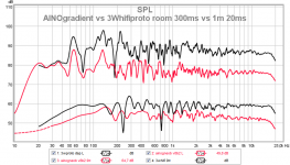
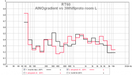
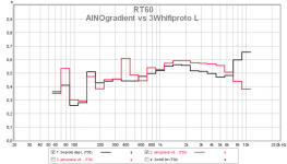
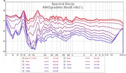
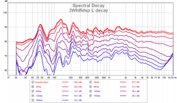
My AINOgradient diy-speakers are crossing monopole bass to dipole mid LR at 120Hz. My 3Whifi proto is just monopole 3-way, double 8" woofers.
I can see the proviously mentioned issues in these measurements clearly. The sound is not so different though. Same location 80cm to front wall, 2m to mic.
I can see the proviously mentioned issues in these measurements clearly. The sound is not so different though. Same location 80cm to front wall, 2m to mic.
Attachments
His recommendation for high-ish damping factor in the amplifiers is not (primarily) for that reason, you understand? His concern is maintaining the designed electrical response so the designed acoustic response yielded is maintained. He's just thinking about consistency of results from various users possibly bringing different combinations of amplifiers together.
That said, in this particular case, the impedance curve of the H1600-04 driver is relatively level throughout the area of usage, so introducing series resistance would still maintain the electrical response but just attenuate it.
Dave.
Part of the reason I mentioned it is because I've got a couple of midwoofers waiting for a box to be built, but in the meantime I put them to good use by the computer in a 'no baffle' configuration, roughly EQ'd in software. Out of curiosity I put a 10ohm resistor in series and found that, despite my logic, it actually seemed to sound better that way, even when correcting the coarse tonal balance with the EQ. So the improved subjective quality had to be caused by something else. And that something didn't sound like harmonic distortion either.
Investigating further, I did some measurements and noticed that the resonant 1k~1.1kHz hump (due to edge diffraction of the 17cm speaker) was not only slightly lower in level with the series resistor connected, but my CSD plots also showed it decaying faster. 50Hz square wave plots were also slightly cleaner with less 1k ringing. So the Q of that resonance had to be lower. I speculate that the resistor allowed the speaker cone to provide soft mechanical damping, whereas 0 ohm would have turned the cone into a hard over-damped surface (0.25Qts) that reflects too much energy. If I can be bothered, I may investigate further and play around with resistor values to see what value makes it critically damped.
How is your resistor damping a resonance in a region where the cone is no longer pistonic?
It's an eton 7-360 hex, so I suspect that the 4kHz break-up resonance might be the real deal. I was wondering how a full-range and/or soft cone driver might fare differently, and honestly I'm not sure. Perhaps even a few grams of cone mass is still enough to produce a sharp discontinuity in the air impedance when a sound wave hits it, but it's very speculative without simulating. Simply EQing the response with biquad filters on a miniDSP is probably a good compromise, it's just a question of how many filters can it do.
On the other hand, I had bad results with a 5 ohm series resistor and a boxed woofer. Lots of comb filtering, mediocre sound. This was also a 'hard' cone. Maybe people get significantly different results with other cone materials, and I can imagine that in those cases, a series resistance might soften some break-up modes by softening the motor's grip on the voice coil.
I guess what I'm trying to understand is how the motor can have an influence on cone breakup that high. The motor can make it go forward and backward as a whole, but not individual sections of it. The cone material itself either has or does not have the ability to dampen the breakup. If the resonance is in the pistonic region, then the motor could be used to dampen it, but I'm not sure.
I guess what I'm trying to understand is how the motor can have an influence on cone breakup that high. The motor can make it go forward and backward as a whole, but not individual sections of it. The cone material itself either has or does not have the ability to dampen the breakup. If the resonance is in the pistonic region, then the motor could be used to dampen it, but I'm not sure.
Still trying to get a handle on it myself. I think once it's 'in break-up' and there are pond-like ripples radiating out from the voice coil to the edge of the cone (and some getting reflected back again), the VC would act like a solid reflective surface because of the strong motor and reduced mass. Flexing paper and plastic would hardly move the VC at all.
My thinking is that a series resistance (or other impedance) could be selected to weaken the motor by just the right amount to provide critical damping at some troublesome frequency. But I'm not sure it's worth tuning it like a passive XO because of the distortion problems people are trying to avoid by going active in the first place!
I seldom post any more but when the door opens...
The LXmini is very similar in concept to a speaker I presented at DIY New England back in 2008 called the Bird House. Monopole woofer crossed into dipole mids with an even order crossover to yield a cardioid response in the transition region. My design was a 3-way with Neo 2 tweeter and I used back to back 4" mids. I commented on it here several times.
http://www.diyaudio.com/forums/multi-way/100392-beyond-ariel-675.html#post2249498
http://www.diyaudio.com/forums/mult...idrange-baffle-width-study-2.html#post1993570
Also made used of the monopole to dipole cardioid transition in my old NaO Mini. NaO Mini Design Objectives "It is also noted that, contrary to other open baffle designs, the Mini uses a sealed box, monopole woofer system. There is sound reasoning behind this. A recent AES article by Backman[1] examined dipole, monopole and cardioid woofer systems with regard to room interaction and sensitivity to listening/system position. His results indicate that in the sparsely populated modal region of the response, which is centered around 100 Hz for a typical listening room, cardioid woofers exhibit the least sensitivity to changes in system or listening position. Backman found dipole woofers to be the most sensitive. Additionally, below the room fundamental Backman shows that the dipole response drops off rapidly due to the inability of a dipole source to pressurize a room. The behavior of cardioid and monopole woofers are similar in nature below the room fundamental, however, the monopole woofer system benefits from higher sensitivity. [This is a result of the 6dB/octave roll off of 1st order gradient type speakers; dipoles and cardioids.] These results are similar to those discussed in the Music and Design articles on Room Response. Backman thus suggests that a woofer system which operates in cardioid mode through the sparsely populated modal region and undergoes a transition to a monopole response below the room fundamental could be optimum for low frequency reproduction."
And I understand that SL has now changed his position on rolling off the top end of his speakers. I recall we had a very long thread about that some time ago where one of my reasons that I disagreed was that if the recording engineers were using speakers which flat response during the mixing process then and such correction should already be in the recording. SL is now saying he was mistaken and apparently was correcting for poor recording.
This is a major reason I don't post anymore. I simply can not believe that so many in the DIY community continue to follow such misdirection, be it from SL or others. Go back and read the extended arguments SL gave about why the top end needed to be rolled off, about how critical the shape of the equalization curve was, how the correction should be adopted by the recording industry, about what a breakthrough this was. And now it's reduced to "I was correcting for bad recording". It's all too laughable. Not SL. He is a tinkerer and he will continue to be such. No, rather it's those in the DIY community who simple choose not to think for themselves and buy into the nonsense.
One challenge is that your posts are hard to follow sometimes. I'm fairly certain that you're 20-40% smarter than most of us, and due to that your posts require a fairly large dose of concentration to understand.
That's not a diss, in fact I refer to your website constantly.
But if you're wondering why your work doesn't get all the accolades it deserves, I think that's part of it.
Just another steady state analysis. Not very usefull in acoustically small rooms.
.
There was a discussion around steady state vs. time domain in this other thread: http://www.diyaudio.com/forums/multi-way/258487-why-crossover-1-4khz-range-14.html#post3986755
As long as we talk about minimum-phase phenomena (modal peaks), steady state determines transient behavior by means of FFT. Mode interferences / reflection cancellations are generally not MP (adding the response of two MP systems is not MP in general), but it looks (see Linkwitz simulations in the above link) that in those cases (quasi) steady state is reached much faster (significantly faster than ear's detection time) and thus the transient response does not matter much anyway.
Thus, steady state seems to rule at LF.
I'm fairly certain that you're 20-40% smarter than most of us
Was this a steady-state or transient measurement ? 😀
- Status
- Not open for further replies.
- Home
- Loudspeakers
- Multi-Way
- New Linkwitz "LXmini" speakers