Dear DIYers
Recently we have released a new revision of our regulators, please take a look
1. New Revision of Dual LT3045 PCB, 0-15V, 1A.
Now it is a bit smaller(24mm x 40mm), Heatsink friendly and can be paralleled for lower noise and higher current output.
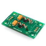
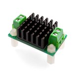
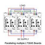
2. Single LT3045 regulator board with fixed output 0-15V. 0.5A - same footprint (24mm x 40mm)
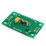
3. Single LT3045 regulator board with configurable output 0-15V. 0.5A - 24mm x 40mm, the output voltage can be configured by DIP switch
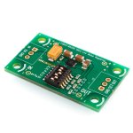
for more details please visit www.ldovr.com
Best regards
and
Happy New Year
Recently we have released a new revision of our regulators, please take a look
1. New Revision of Dual LT3045 PCB, 0-15V, 1A.
Now it is a bit smaller(24mm x 40mm), Heatsink friendly and can be paralleled for lower noise and higher current output.


2. Single LT3045 regulator board with fixed output 0-15V. 0.5A - same footprint (24mm x 40mm)

3. Single LT3045 regulator board with configurable output 0-15V. 0.5A - 24mm x 40mm, the output voltage can be configured by DIP switch

for more details please visit www.ldovr.com
Best regards
and
Happy New Year
As ldovr wont answer my support request mails - I'll try here...
I have pair of ldovr boards LT3045-M that I would like to strap, one for 5v and one for 3,3v.
There is no instruction available and only the print on the board... what do you make out of it..
Straps positions on board in 2 vertical rows:
____ R5
R1
____ R4
R2
____ R3
then a list of voltages:
0.3
1
2
4
8V
How do you reckon the 2 list relate?
is it (a):
R5 - 0,3
R1 - 1
R4 - 2
R2 - 4
R3 - 8V
or (b)
R1 - 0,3
R2 - 1
R3 - 2
R4 - 4
R5 - 8V
or other arrangement?
My particular board in the picture - is that for 15,3V?
I suppose the R1-R5 are 0 (zero) ohm resistors - is this correct?
For 5 volt, should only resistor R2 and R4 be present and the others removed??
Help!!
//
OK - found some instructions... but it does not really help as "from TOP" is unclear...
Is R5 = the top in "from TOP" and next is R1? (Why is top written like "TOP"? strange...)
Vout = sum of open pins... OK!
So I would like 1v and 4v too be open so I take away R1 and R2?
This could have been so easy...
//

Is R5 = the top in "from TOP" and next is R1? (Why is top written like "TOP"? strange...)
Vout = sum of open pins... OK!
So I would like 1v and 4v too be open so I take away R1 and R2?
This could have been so easy...
//
Can these be placed in series, to get higher voltages, as well as paralleled? Thinking of a bank of these....
Perhaps it is the pads between the resistors that should be shorted to program this?
Thats make more sense perhaps - but why not write it out!!???
//

Thats make more sense perhaps - but why not write it out!!???
//
We are happy to announce that, in response to numerous requests, we have released the new LT3094 Low Noise Voltage Regulator PCB with negative output. This product is designed to perfectly match our highly popular LT3045-1A0G regulator.
Key Features:
Wide Input Voltage Range: -1.8V to -20V
Output Voltage Range: 0V to -19.5V
Output Current: 1A
Low Dropout Voltage: 235mV
Ultralow RMS Noise: ~0.58µVRMS (10Hz to 100kHz)
Ultralow Spot Noise: 2nV/√Hz at 10kHz
Ultrahigh PSRR: 74dB at 1MHz
Single Resistor Programs Output Voltage
Built-In Fixed Current Limit and Thermal Shutdown
Parallelable for Lower Noise and Higher Current
PCB size: 24mm x 40mm
Operating Temperature Range:–40°C to 125°C
Can be paralleled in the same manner as the LT3045, offering greater flexibility and scalability for your power supply designs.
https://www.ldovr.com/product-p/lt3094-1a0g.htm
Introducing the Silent Switcher - an extremely efficient solution, especially when you need to step down voltage (e.g., 15V DC to 5V DC @ 3A output, all without a heatsink!). It's also ideal as a preregulator for our low-noise linear regulators.

- Silent Switcher® Architecture
- Ultralow EMI Emissions
- Optional Spread Spectrum Modulation
- High Efficiency at High Frequency
- Up to 95% Efficiency at 2MHz, 12VIN to 5VOUT
- Wide Input Voltage Range: 5.5V to 35V
- 3A Maximum Continuous, 6A Peak Output
- Output Ripple < 10mVP-P
- Fast Transient Response
- Fast Minimum Switch On-Time: 30ns
- Low Dropout Under All Conditions: 100mV at 1A
- Home
- Vendor's Bazaar
- New ldovr.com power modules (LT3045/LT3094/TPS7A4700/TPS7A3301)