Russ,
I am trying to understand the reason for the resistors on the pcb, they would always be across the input to ground except for the input that that was active adding to load presented to the source. They are probably not needed or were they ment to be in series with the input.
Regards,
Jam
I am trying to understand the reason for the resistors on the pcb, they would always be across the input to ground except for the input that that was active adding to load presented to the source. They are probably not needed or were they ment to be in series with the input.
Regards,
Jam
jam said:Russ,
I am trying to understand the reason for the resistors on the pcb, they would always be across the input to ground except for the input that that was active adding to load presented to the source. They are probably not needed or were they ment to be in series with the input.
Regards,
Jam
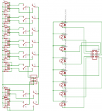
They are there simply to provide a high impedance (100K or so) GND reference for unused sources and ouputs. They are only active when a source/output is "off". Some sources don't like "open" loads, and most amplifiers don't like open inputs. So really I am just keeping any inactive input/outputs from floating.
They can of course be omitted.
Cheers!
Russ
Russ,
I understand your reasoning but to me then the switches need to be redrawn or the resistors tied directly to the inputs..............or maybe I am missing something?
Regards,
Jam
I understand your reasoning but to me then the switches need to be redrawn or the resistors tied directly to the inputs..............or maybe I am missing something?
Regards,
Jam
jam said:Russ,
I understand your reasoning but to me then the switches need to be redrawn or the resistors tied directly to the inputs..............or maybe I am missing something?
Regards,
Jam
You are correct. It has been fixed thanks!!!
Russ,
Works for me................just a thought but you could rewire the unused pin on the relay to short non-active inputs to ground thus eleminating a potential source of cross talk...........but then again some sources might not like their outputs shorted........😉
Regards,
Jam
Works for me................just a thought but you could rewire the unused pin on the relay to short non-active inputs to ground thus eleminating a potential source of cross talk...........but then again some sources might not like their outputs shorted........😉
Regards,
Jam
jam said:Russ,
but then again some sources might not like their outputs shorted........😉
Hi Jam,
Thank you very much for your input. I think the layout is safest the way it is. I don't want to have explain to every person who builds one of these which sources can be shorted and which can't. I think I will leave it as is and if some want to they can very easily throw on a jumper or a resistor from that pin to GND.
Cheers!
Russ
Hawaii said:When will the kit be ready for shipping?
Can't wait to build it... 😀
Soon. Very soon. 🙂
I was at your site yesterday, prepaid for a kit and returned later that day and noticed another relay board has been added. What is the function of the second relay board?
Member
Joined 2002
moreismore said:I was at your site yesterday, prepaid for a kit and returned later that day and noticed another relay board has been added. What is the function of the second relay board?
Are you talking about the input selector one or the volume relay board ?
Jase
Member
Joined 2002
moreismore said:Yes, the Darwin input selector.
I don't want to assume but i would think the extra board is so you can use it in balanced mode. 🙂
The second relay board is for balanced operation. With one relay board, you can do single-ended (R+, GND, L+). With two boards, one would switch R+, GND, R-, the other L+, GND, L-.
It was my mistake in not posting it correctly the first time. If you need balanced operation and already ordered, send me an email and we can work something out.
It was my mistake in not posting it correctly the first time. If you need balanced operation and already ordered, send me an email and we can work something out.
Member
Joined 2002
BrianDonegan said:The second relay board is for balanced operation. With one relay board, you can do single-ended (R+, GND, L+). With two boards, one would switch R+, GND, R-, the other L+, GND, L-.
It was my mistake in not posting it correctly the first time. If you need balanced operation and already ordered, send me an email and we can work something out.
And this is a perfect example of how Brian / Russ are ding such a good job.
Keep it up guy's.
Jase
Kits
Here's a pic of the relay board with kit parts:
Not shown in the pic are the two rotary switches (6-pos, 2-deck and 3-pos 4-deck) and the IDC wiring connector.
Here's a pic of the relay board with kit parts:
An externally hosted image should be here but it was not working when we last tested it.
Not shown in the pic are the two rotary switches (6-pos, 2-deck and 3-pos 4-deck) and the IDC wiring connector.
Member
Joined 2002
Re: Kits
Yet another nice kit.. Look for my order soon 🙂
BrianDonegan said:Here's a pic of the relay board with kit parts:
An externally hosted image should be here but it was not working when we last tested it.
Not shown in the pic are the two rotary switches (6-pos, 2-deck and 3-pos 4-deck) and the IDC wiring connector.
Yet another nice kit.. Look for my order soon 🙂
- Status
- Not open for further replies.
- Home
- Amplifiers
- Chip Amps
- New input/output Selector