Heaters for direct heated triodes can be DC or AC (50/60Hz).
AC is often used because of more linaerity and more lifeness, but it also modulates the input signal with the line frequency and its harmonics.
DC is prefered to eliminate the hum on the output, but loads the cathode unsymetrically.
I have a new idea which I will try in my next design: single stage AD1 or 2A3 (I do not know if this is really new, maybe somebody has it already done).
Why not use AC without hum?!
The idea is to use a high frequency powered heater above the audible band, lets say about 200 - 500KHz. A simple oscillator and a full bridge motor driver IC can do the job. Devices like
National LMD18201 or
ST L6202 should do it.
What do you think about it? All ideas appreciated
Thanks Emil
Everything is worth trying at least once I guess.. I try hard to eliminate sources of rf interference from my amps rather than introduce them though.
The problem with rf noise is that although you can't hear it, the tubes in your amp are more than capable of operating at those frequencies.
At higher frequencies screening is much more difficult to acheive as wiring and components make quite good aerials.
I have played with switchmode power supplies in transistor amps - the result is usually good but not great. Fine detail is compromised and there's a hardness to the sound which you don't get with a linear supply. I suspect you might get similar results here.
Good luck - I would be interested to know how it all turns out if you go ahead with the design
Hi,
Jim Hagerman of Hagtech is working on a similar supply for DHT's.
So far I think he's working on something in the region of 50KHz.
What I'm wondering about is that, as far as the tube is concerned, the higher you push the pulse frequency of that heater supply the more it's going to look as if it's a DC supply, isn't it?
Cheers,")
Jim Hagerman of Hagtech is working on a similar supply for DHT's.
So far I think he's working on something in the region of 50KHz.
What I'm wondering about is that, as far as the tube is concerned, the higher you push the pulse frequency of that heater supply the more it's going to look as if it's a DC supply, isn't it?
Cheers,
Hmm, or do I mean screee? If you apply a 200kHz sine wave (don't let's even think about square waves) across the cathode of a DHT, any imbalance of capacitances will mean that you are driving a grounded grid stage from the cathode. Thing is, grounded grid stages have lots of bandwidth because Miller efect isn't an issue. Imbalances in the output transformer (almost a certainty at that frequency) mean that you will modulate the HT supply. Which will have non-zero impedance at 200kHz...
I see where you're coming from regarding 50/60Hz problems, but going to RF won't be a cure-all. You'll have all sorts of RF problems to solve because of the hidden imperfections of real components. I'm not an RF whizz, so I don't consider that to be easy.
I see where you're coming from regarding 50/60Hz problems, but going to RF won't be a cure-all. You'll have all sorts of RF problems to solve because of the hidden imperfections of real components. I'm not an RF whizz, so I don't consider that to be easy.
I do not know if this is really new, maybe somebody has it already done.
It has been done many times. I find the idea daft but many diyers seem happy with the result so there probably is something in it
Ultrasonic Heaters
I agree with EC8010. If you're a good RF angineer and have some decent measuring facilities, then it might be possible to make it work really well. But I don't think it will be plug-n-play and each individual amp installation might need to be tweaked to make it work to it's best.
I don't see what the problem with DC is?
If you use two equal valued resistors to connect each side of the cathode to the circuit, provided they are low enough, this should not be a problem. Ok the resistors may have to be a higher wattage, but there is plenty of heat in a valve amplifier anyway, so what's a little more heat?
If you use two equal valued resistors to connect each side of the cathode to the circuit, provided they are low enough, this should not be a problem. Ok the resistors may have to be a higher wattage, but there is plenty of heat in a valve amplifier anyway, so what's a little more heat?
A hatred of silicon?
NOt necessarily
A Japanese gentleman has come up with nice DC heaters for his 300B amp
Attachments
Konnichiwa,
I do not neccesarily see this as problem, it is a quatstion of implementation.
It is certainly doable.
You are facing a few issues to resolve though:
1) You need to select a frequency where any difference tones with typhical clock signals in digital audio will not fall into the audio band.
2) You need to enforce a more or less ideal symmetry for RF which will result in some capacitive load for the system, enough load to be potentially worrysome.
3) You need to make sure your signal is either a nice sinewave (inefficient in the largest degree) or an accuratly 50/50 duty cycle squarewave.
4) You need to manage RF emission.
You gain some things in return:
1) No Hum. If your capacitive RF symmetry works well you also do not get any material switching/modulation frequency breakthrough.
2) You can make a central RF supply (even from a modified electronic transformer for 12V Halogen lighting) with small local torroidal transformers, directly local on the valve sockets with a few turns of bare silver wire as balanced secondary, making the best possible cathode connecting device.
I think for most DIY'ers DC is a much easier option to get right, but if you where to make amplifiers commercially I suspect the benefits on cost, size and efficiency may very well be worth working out this gig to a T....
Sayonara
kekso22 said:DC is prefered to eliminate the hum on the output, but loads the cathode unsymetrically.
I do not neccesarily see this as problem, it is a quatstion of implementation.
kekso22 said:The idea is to use a high frequency powered heater above the audible band, lets say about 200 - 500KHz. A simple oscillator and a full bridge motor driver IC can do the job. Devices like
National LMD18201 or ST L6202 should do it. What do you think about it? All ideas appreciated
It is certainly doable.
You are facing a few issues to resolve though:
1) You need to select a frequency where any difference tones with typhical clock signals in digital audio will not fall into the audio band.
2) You need to enforce a more or less ideal symmetry for RF which will result in some capacitive load for the system, enough load to be potentially worrysome.
3) You need to make sure your signal is either a nice sinewave (inefficient in the largest degree) or an accuratly 50/50 duty cycle squarewave.
4) You need to manage RF emission.
You gain some things in return:
1) No Hum. If your capacitive RF symmetry works well you also do not get any material switching/modulation frequency breakthrough.
2) You can make a central RF supply (even from a modified electronic transformer for 12V Halogen lighting) with small local torroidal transformers, directly local on the valve sockets with a few turns of bare silver wire as balanced secondary, making the best possible cathode connecting device.
I think for most DIY'ers DC is a much easier option to get right, but if you where to make amplifiers commercially I suspect the benefits on cost, size and efficiency may very well be worth working out this gig to a T....
Sayonara
I think that DC heating is by far not the best way.
I imaging that the voltage drop across the cathode from the DC supply make things bad.
Lets assume that the DC filament is 5V. I split the triode in 2 pieces and connect this 2 tubes in parallel. One tubes has now a grid voltage which is 5V lower than the other. At high grid levels, lets say 100V, one tube makes 100% current (100V grid), the other makes about 5% less (95V grid). At low grid voltages, lets say 20V, one tube is again at 100%, but the other now only works at 75%. This nonlinearity makes distortion.
AC heating should be much better, but now the 50Hz is modulated with the input signal and makes sidebands with 50Hz spacing. Even worse, the cathode is heated up and down with 100Hz, which makes a variation of the emission and the input signal is modulated with 100Hz either.
For me the switching frequency of a RF heater should be as high as possible. 50 or 60KHz is not sufficient, because the 3rd overtone with a 20KHz input signal is already in the audible band.
It should be a minimum of 10 times higher. Choosing a frequency which is not close at radio or DAC switching frequencies (96Khz,192KHz...) is a good idea. If its high enough anyway, the lowpass of the grid will filter it out. I also disagree that a symmetrical or sinus
wave form is necessary. This will give only harmonics witch are above.
Am I wrong or do I have missed something?
Thanks
Konnichiwa,
Well, it seems WE in the 1930's disagreed with you.
Why?
NO. You MUST if you will split the triode into 8pcs for the 300B for example, due to the centertapped filament there will be around 4 pairs of triodes with more or less similar behaviour in terms of voltage.
But note that the mechanical structure of most real valves I have seen has sufficient variation to suggest that all 8 of these "seperate" triodes all will show electrical parameters of sufficient difference to make each of these 8 Triodes to behave very different electrically regardless of AC or DC filaments.
That is simply not true. Full stop. You analysis is completely out and note that most manufacturers (WE most certainly) derived their curved with the negative filament grounded and DC applied to heating.
Why? Because instead of a static deviation of opertaing condition the between the various parallel "sub-triodes" within the Valve you now have the same varitions modulated 50/60/50000 times the second?
So, if it is a static condition it causes distortion, but if it is a dynamically modulated condition it does not cause distortion? Simple measurements taken will disabuse you of this notion.
???!!! I fail to follow.
???!!! Again, I fail to follow. I agree that a sinewave is not neccesary (or possibly even desirable?!), but I am not getting your point.
Yes, you ARE wrong.
Yes, you choose to use a model abstracted far beyond usefulness from the real situation and you ignored completely how real valves are constructed. As a result you conclusions are unusable in reality.
BTW, while I largerely agree in thinking that RF heating is a neat trick, it does carry many problems included as well and I repeat, for the average (and advanced) DIY'er using DC is a much more reliable and predicatble way of making an Amplifier that is quiet and sounds good.
Sayonara
kekso22 said:I think that DC heating is by far not the best way.
Well, it seems WE in the 1930's disagreed with you.
kekso22 said:I imaging that the voltage drop across the cathode from the DC supply make things bad.
Why?
kekso22 said:Lets assume that the DC filament is 5V. I split the triode in 2 pieces and connect this 2 tubes in parallel.
NO. You MUST if you will split the triode into 8pcs for the 300B for example, due to the centertapped filament there will be around 4 pairs of triodes with more or less similar behaviour in terms of voltage.
But note that the mechanical structure of most real valves I have seen has sufficient variation to suggest that all 8 of these "seperate" triodes all will show electrical parameters of sufficient difference to make each of these 8 Triodes to behave very different electrically regardless of AC or DC filaments.
kekso22 said:One tubes has now a grid voltage which is 5V lower than the other. At high grid levels, lets say 100V, one tube makes 100% current (100V grid), the other makes about 5% less (95V grid). At low grid voltages, lets say 20V, one tube is again at 100%, but the other now only works at 75%. This nonlinearity makes distortion.
That is simply not true. Full stop. You analysis is completely out and note that most manufacturers (WE most certainly) derived their curved with the negative filament grounded and DC applied to heating.
kekso22 said:AC heating should be much better,
Why? Because instead of a static deviation of opertaing condition the between the various parallel "sub-triodes" within the Valve you now have the same varitions modulated 50/60/50000 times the second?
So, if it is a static condition it causes distortion, but if it is a dynamically modulated condition it does not cause distortion? Simple measurements taken will disabuse you of this notion.
kekso22 said:For me the switching frequency of a RF heater should be as high as possible. 50 or 60KHz is not sufficient, because the 3rd overtone with a 20KHz input signal is already in the audible band.
???!!! I fail to follow.
kekso22 said:I also disagree that a symmetrical or sinus wave form is necessary. This will give only harmonics witch are above.
???!!! Again, I fail to follow. I agree that a sinewave is not neccesary (or possibly even desirable?!), but I am not getting your point.
kekso22 said:Am I wrong
Yes, you ARE wrong.
kekso22 said:or do I have missed something?
Yes, you choose to use a model abstracted far beyond usefulness from the real situation and you ignored completely how real valves are constructed. As a result you conclusions are unusable in reality.
BTW, while I largerely agree in thinking that RF heating is a neat trick, it does carry many problems included as well and I repeat, for the average (and advanced) DIY'er using DC is a much more reliable and predicatble way of making an Amplifier that is quiet and sounds good.
Sayonara
Hi Kuei,
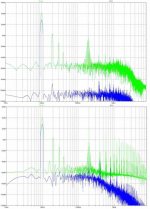
I have done a quick Spice simulation to show what I mean with the heater frequency must be high enough and even DC switching does not hurt.
1.page:
input signal 10KHz; cathode 5V heater @200KHz sinus
(generates no audible signals)
2.page:
input signal 10KHz; cathode 5V heater @200KHz DC switched
(also no problem)
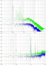
3.page:
input signal 10KHz; cathode 5V heater @45KHz sinus
(heater comes in at 15KHz)
4.page:
input signal 1KHz; cathode 5V heater @50Hz sinus
(humm @50, 100Hz and modulation around 1KHz; 950,1050,900Hz...)
The results show that also a 10Hz heater is the wrong way.
Maybe with the DC heater supply I am wrong. I will do a some Spice (seems difficult) and I will post the results.
I have done a quick Spice simulation to show what I mean with the heater frequency must be high enough and even DC switching does not hurt.
1.page:
input signal 10KHz; cathode 5V heater @200KHz sinus
(generates no audible signals)
2.page:
input signal 10KHz; cathode 5V heater @200KHz DC switched
(also no problem)
3.page:
input signal 10KHz; cathode 5V heater @45KHz sinus
(heater comes in at 15KHz)
4.page:
input signal 1KHz; cathode 5V heater @50Hz sinus
(humm @50, 100Hz and modulation around 1KHz; 950,1050,900Hz...)
The results show that also a 10Hz heater is the wrong way.
Maybe with the DC heater supply I am wrong. I will do a some Spice (seems difficult) and I will post the results.
Attachments
Konnichiwa,
I still question you basic assumptions which no doubt have influenced your Spice Models.
Let me repeat, if you actually take a real 300B and test it at 50Hz you find that you buck out (make common mode) the 50Hz fundamental very effectively, making it sufficiently disappear that we need not worry about it. The same will hold true for any RF Heating fundamental, however one may require some form of adjustable capacitive "hum bucking" to get the balance right.
If we use the frequency I commonly recommend (76.5KHz) for the RF supply you also avoid any issues with difference products folding back.
However, it is a comparably high tech solution which has no real advantages over a more traditional well filtered DC Heater, at least outside commercial manufatcurerd gear.
And I repeat that I fail to observe any issues with a static deflection of the operating conditions of a given "sub-triode" within the main envelope, as cause by DC heating.
For arguments sake, I found two approaches to DC heating to sound as good as AC Heating but without the softening of sound and the general haziness and indistinctness AC hetaing brings.
1) Use Schottky Diodes & CLC as well as CMC Filtering to minimise noise and to keep any mains related nosie components low order. Use with classic balancing network (adjustable preferred) and noise can be extremely low.
2) Use schottky diodes with C Filtering plus CMC filtering (CMC filtering is essential even with AC BTW) and a regulator. Connect the cathode resistors to the negative side of the filament but connect the cathode bypass capacitor to the positive side of the filament. This was shown by JC Verdier and I found it to be a major step forward on (voltage and current) regulated DHT heater circuits.
Both approaches seem to show non of the negative sides usually ascribed to (and also observed by me) to DC heating.
I must agree that the traditional methode with a cheap bridge and a single 10,000uF Cap usually seen for the 300B is absolutely abysimal and sounds a lot worse than AC, edgy, agressive and hazy. The reason becomes quickly obvious if you put a 'scope on the filament or better do an FFT of both the error current flowing into the cathode/ground (and thus grid) loop of the output stage and of the voltage across the filament....
Sayonara
kekso22 said:Hi Kuei,
I have done a quick Spice simulation to show what I mean with the heater frequency must be high enough and even DC switching does not hurt.
I still question you basic assumptions which no doubt have influenced your Spice Models.
Let me repeat, if you actually take a real 300B and test it at 50Hz you find that you buck out (make common mode) the 50Hz fundamental very effectively, making it sufficiently disappear that we need not worry about it. The same will hold true for any RF Heating fundamental, however one may require some form of adjustable capacitive "hum bucking" to get the balance right.
If we use the frequency I commonly recommend (76.5KHz) for the RF supply you also avoid any issues with difference products folding back.
However, it is a comparably high tech solution which has no real advantages over a more traditional well filtered DC Heater, at least outside commercial manufatcurerd gear.
And I repeat that I fail to observe any issues with a static deflection of the operating conditions of a given "sub-triode" within the main envelope, as cause by DC heating.
For arguments sake, I found two approaches to DC heating to sound as good as AC Heating but without the softening of sound and the general haziness and indistinctness AC hetaing brings.
1) Use Schottky Diodes & CLC as well as CMC Filtering to minimise noise and to keep any mains related nosie components low order. Use with classic balancing network (adjustable preferred) and noise can be extremely low.
2) Use schottky diodes with C Filtering plus CMC filtering (CMC filtering is essential even with AC BTW) and a regulator. Connect the cathode resistors to the negative side of the filament but connect the cathode bypass capacitor to the positive side of the filament. This was shown by JC Verdier and I found it to be a major step forward on (voltage and current) regulated DHT heater circuits.
Both approaches seem to show non of the negative sides usually ascribed to (and also observed by me) to DC heating.
I must agree that the traditional methode with a cheap bridge and a single 10,000uF Cap usually seen for the 300B is absolutely abysimal and sounds a lot worse than AC, edgy, agressive and hazy. The reason becomes quickly obvious if you put a 'scope on the filament or better do an FFT of both the error current flowing into the cathode/ground (and thus grid) loop of the output stage and of the voltage across the filament....
Sayonara
After some brainstormingOriginally posted by Kuei Yang Wang
For arguments sake, I found two approaches to DC heating to sound as good as AC Heating but without the softening of sound and the general haziness and indistinctness AC hetaing brings.
I found that I was wrong with my thoughts about DC heating.Splitting a triode into several pieces and with every sub-triode having a different cathode-grid voltage makes only a small variation of the operation points and no distortion!!
For me its now clear that DC should be the best way to go.
Use schottky diodes with C Filtering plus CMC filtering (CMC filtering is essential even with AC BTW) and a regulator. Connect the cathode resistors to the negative side of the filament but connect the cathode bypass capacitor to the positive side of the filament. This was shown by JC Verdier and I found it to be a major step forward on (voltage and current) regulated DHT heater circuits.
This sounds good to me, I will try it. Can you please tell me what you mean with CMC filtering.
Thanks
Konnichiwa,
Yes, that is what I referred to. However, the big caveat is that DC Heating requires pretty pure DC. Batteries are a good one, approaching this with conventional supplies is a major headache.
CMC = Common Mode Choke.
One key problem with heating a DHT from a mains supply (AC or DC) is that there are usually quite a few 10uA to 1mA leakage of noise (50Hz all the way to FM range) into the secondary circuit referenced to earth/ground. This current is in dact injected into the cathode. The 50Hz leakage can be dealt with much easier than HF leakage. Common Mode filtering removes some of that noise.
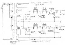
My current 300B SE Amp which uses DC on the heaters (like most of my designs) is here:
http://www.audioasylum.com/forums/tubediy/messages/71898.html
The heater circuit is shown here as part of the whole schematic:
To see the kind of chokes used look at this Photo:
BTW, while I do give thumbs up to well implemented DC heaters, I remain curious about HFAC Heaters and will eventually experiment with them. I'm also interested in using switched mode supplies for the HT which would give a convenient source of HFAC to heat the valves as well.
This post may interest you:
http://www.diyaudio.com/forums/showthread.php?postid=576778#post576778
Sayonara
kekso22 said:After some brainstorming
Splitting a triode into several pieces and with every sub-triode having a different cathode-grid voltage makes only a small variation of the operation points and no distortion!!
Yes, that is what I referred to. However, the big caveat is that DC Heating requires pretty pure DC. Batteries are a good one, approaching this with conventional supplies is a major headache.
kekso22 said:This sounds good to me, I will try it. Can you please tell me what you mean with CMC filtering.
CMC = Common Mode Choke.
One key problem with heating a DHT from a mains supply (AC or DC) is that there are usually quite a few 10uA to 1mA leakage of noise (50Hz all the way to FM range) into the secondary circuit referenced to earth/ground. This current is in dact injected into the cathode. The 50Hz leakage can be dealt with much easier than HF leakage. Common Mode filtering removes some of that noise.
My current 300B SE Amp which uses DC on the heaters (like most of my designs) is here:
http://www.audioasylum.com/forums/tubediy/messages/71898.html
The heater circuit is shown here as part of the whole schematic:
An externally hosted image should be here but it was not working when we last tested it.
To see the kind of chokes used look at this Photo:
An externally hosted image should be here but it was not working when we last tested it.
BTW, while I do give thumbs up to well implemented DC heaters, I remain curious about HFAC Heaters and will eventually experiment with them. I'm also interested in using switched mode supplies for the HT which would give a convenient source of HFAC to heat the valves as well.
This post may interest you:
http://www.diyaudio.com/forums/showthread.php?postid=576778#post576778
Sayonara
@ Kuei
...and what's the max current the chokes can swallow and the ripple you get? Should be at least something about 6A. I am just making a few calculations for a 2A3 DC heater and found something like 2.5mH/10A : my scheme is LC + CMC + regulator + LC (high freq) btw.
Gianluca
...and what's the max current the chokes can swallow and the ripple you get? Should be at least something about 6A. I am just making a few calculations for a 2A3 DC heater and found something like 2.5mH/10A : my scheme is LC + CMC + regulator + LC (high freq) btw.
Gianluca
- Status
- This old topic is closed. If you want to reopen this topic, contact a moderator using the "Report Post" button.
- Home
- Amplifiers
- Tubes / Valves
- new idea of DHT heater supply