Guy's
Here is the lastest design which I like a lot and may try to build. The heat sink can be built by hand with a benchtop drill press and 2-way mill type sliders. Another more effective heat sink design can be made but with more labor to built it. It is wire type.
I believe this could work with no fans for 250 watt or even 400 watt bulb. If high quality heat glass is used. A 3 x 3 inch square is required in this configuration.
The light sink brackets are of course aluminum to convey heat to the larger heat sink.
Now my next goal is to try and fiqure out a way to effectively recycle the light inside the light pipe so both polarization states are used by the LCD.
Hezz
Attachments
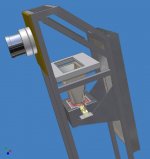
I decided that I need to have a design that is easier to build with hand tools and can be built with little or no machine tools. After spending several days at an optical comparator on my new part time job I came to the conclusion that the focusing mechanism was very important to get a high resolution picture. Deviations as little .0001" seem to effect the focus significantly.
I started machining a new lens mount and adjuster out of aluminum and a scrap piece of polyethylene that I got from work. Here is the new projector work up but no pictures of the new lens mount yet. I will show it when it is done if I get the threads to work. They are 3 7/16 - 16 UN class 3 threads and will have nearly no loosenes or play.
The open finned area is going to have a quiet 120 mm fan mounted there but not shown. I have an extra Panaflo around that I will try at reduced RPM.
Hezz
Attachments
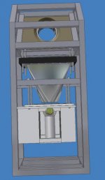
Here is another picture from the side showing the light heatsink assembly and hand made bulb cooler. It is shown without the side cover that has a bulb mount located on it's side to hold the bulb in place.
I fiqure that I can have the reflector pedestal made at any or different sizes to adjust it's position and then hold it steady. It will probably be a hollow aluminium tube with some kind of ancoring mechanism on the bottom end. The reflector will probably be glued with high temp RTV silicone once the right location is found.
Hezz
Attachments
Ok guys,
I have slowly started working on this projector but I still need to get the LCD and some othr parts. I am building a dedicated HTPC to drive the LCD panel because I don't want to have to change cabling around with the other family room PC every time I want to watch a movie.
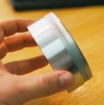
Here are some snapshots of the lens mount that I am building for the surplus shed 240 mm copier lens. The pictures turned out bad because I bought this cheap grainy 400 ASA film from Fred Meyer. I will not use it again.
This is the bottom of the lens mount.
Hezz
I have slowly started working on this projector but I still need to get the LCD and some othr parts. I am building a dedicated HTPC to drive the LCD panel because I don't want to have to change cabling around with the other family room PC every time I want to watch a movie.
Here are some snapshots of the lens mount that I am building for the surplus shed 240 mm copier lens. The pictures turned out bad because I bought this cheap grainy 400 ASA film from Fred Meyer. I will not use it again.
This is the bottom of the lens mount.
Hezz
Attachments
And finally,
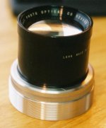
Here is the aluminum lens mount with the surplus shed lens sitting in it's place. There is about .002 inch clearance between the lens housing and the lens mount. I have not yet decided how to hold the lens in place. I will either tap four set screws around the perimeter of the knurled area or I may just glue it in with silicone glue.
Hezz
Attachments
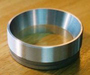
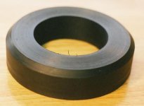
The female lens mounting bracket will be machined out of a piece of scrapped black polyethelyne plastic that was a scrapped pump head from work.
I have not turned the inner diameter or threaded it yet to the correct size. Then four mounting holes will be drilled and countersunk into the perimeter or the bracket.
I though that this plastic would make a good mounting flange because the plastic is softer and more pliable than the aluminum and so the threads can be made tight because the plastic will give a little.
Hezz
Attachments
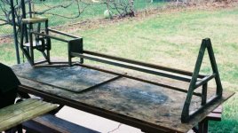
Here is a picture of my first frame iteration. I decided that it was to hard to experiment with so I am scrapping it for another frame design. Plus I was in a hurry and the frame does not sit square although that can be remedied. If anyone wants this frame they can have it if they arrainge to pick it up.
Hezz
Hezz
Attachments
Here are my lastest design ideas for the light engine. I think that I am scraping the spherical reflector for a parabolic that will be designed specifically to work as well as possible with a 250 watt double ended HQI.
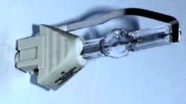
The bulb will be mounted in an unusual way in a vertical orientation.
The reflector is designed to be a heat sink as well as a shield for the bulb so that the cold outside air moving from the main heatsink does not flow around the bulb directly and cause it to cool to rapidly.
The hot air surrounding the bulb can be gradually replaced by cooler air from a small amount of cooler air that flows over the top of the reflector in a gap there. The hot air inside the reflector can also bleed off heat slowly into the reflector which is cooled by the moving air. The condenser FL's will need to be adjusted for this design.
Hezz
Attachments
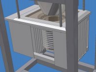
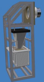
The opened finned area on the right hand side of the large heatsink is where a 120 mm Panaflo or Silenx fan will be mounted.
The large heatsink will have a hot mirror or an IR glass filter.
Condenser lens is mounted inside of the light paramid to act as a mount and a heat sink for the condenser lens.
Here is a picture of the proposed vertical HQI mounting scheme so it will work with the parabolic reflector.l
The large heatsink is shown with some cover plates removed for visual access.
Hezz
Attachments
- Status
- Not open for further replies.
- Home
- General Interest
- Everything Else
- The Moving Image
- DIY Projectors
- New High end 7" LCD projector design proposal