Guys,
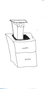
I will post information here on the small LCD projector that I have actually started on. It is an upright standing metal frame projector that will use a 7 inch 16:9 LCD and the surplus shed fujinon copier lens with 240 FL. The light engine will be a new modified version of a point source light source.
Hezz
Attachments
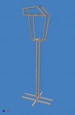
Although the projector frame looks like it may be heavy it is constructed out of 3/4 inch hollow tubular metal. The metal cost about 15 USD and I already had it laying around. I expect the frame will weigh no more than twenty five pounds so it will not have castors to roll it around.
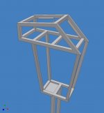
Here's another close up. I will post a sketch of the light engine concept and some pictures of the actual work I have done so far.
Hezz
Here's another close up. I will post a sketch of the light engine concept and some pictures of the actual work I have done so far.
Hezz
Attachments
Guys,
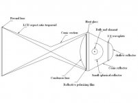
Here is a sketch of my light engine concept. The condenser lens is not exactly to scale as far as it's focal length so don't be mislead but is a close approximation. I have some ideas about the wavequide trapaziods and conical sections. Basically they take any non incident light rays and redirect them into the fresnel at a close to desirable angle. An attempt to recycle the out of polar light is attempted before the condenser lens.
Hezz
Attachments
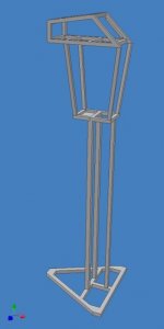
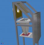
I have decided to modify the frame somewhat because I don't have the necessary jigs or time to get the frame perfectly square so I will need to be able to adjust the base with threaded feet to level out the projector if necessary. This is the new design.
I have the top section all welded together but need to do a lot of rust removal and weld preperation.
The new three point base arraingement will allow me to get better stability and level the thing out on uneven ground. One thing is that I don't want the projector to rock when people walk around near it on the floor when others are watching a move.
Hezz
Attachments
I like your design hezz, its very practical, nice work.
I hit you with an email the other day too, let me know if you got it.
Trev
I hit you with an email the other day too, let me know if you got it.
Trev
Trev,
For some reason I never got your e-mail. Maybe this forum still has my old one. I will check it out.
Nmd,
I like your idea but for me I like light weight special purpose designs. Don't apologize about your sketch. I make bad idea sketches myself and when I get a new idea I almost always sketch it out before I start to model on the computer.
Hezz
I have what may be a more elegant solution to your adjustable feet. The problem I see with this is that while leveling the projector as needed with the feet you might have to have your vertical column out of level, which would make your whole projector more susceptable to tipping.
I would look on ebay for a nice video tripod head with a ball mount adjustment. Use this to mount the upper projector portion to the vertical column, and then you can easily make any minor adjustments with the tripod head instead. You could even still use adjustable feet to make sure the lower portion was perfectly level, in case the floor it's on is uneven.
Might add more cost than intended to your PJ, but it would be a nice solution I think.
Another nice thing about the tripod head is it would make taking the upper portion off the base very easy, in case you had to do any major changes to the pj.
Faithblinded,
That's a good idea except that I've already welded the vertical sections to upper frame. I will only need about 1/4 inch of adjustment because the frame is close to being on. I figure the cheapest and easiest way is to just tap some threads on the three corners of the stand and use bolts with feet on them. It can then be leveled in any direction within reason. If the vertical columns are out a small amount it won't matter as it will be too little to notice by looking at it.
I am trying to make a threaded mount for the lens and have got one made out of PVC conduit male and female threaded nipple. I now have to test it and see if the mount will interfere with the image light rays. This might end up being the hardest part next to figuring out what light engine configuration to use.
It's a pain when you don't have a machine shop to make your own custom parts. By the way, the frame feels like it's only going to weigh about 18-20 pound without any internal stuff so it won't be too heavy.
Trev,
My e-mail address was the old one but I have since edited it. You can now try and send a message.
Hezz
"Xenarc" TFT
http://www.digitalww.com/edtcb18.pdf
CR 150:1
RT 56 ms
http://www.digitalww.com/images/VGAM_LCD5.JPG
http://www.digitalww.com/images/VGAM_LCD3.JPG
Source:
http://www.mp3car.com/vbulletin/showthread.php?t=12105
This one (TM_710VG) is better with 200:1 CR and 30 ms RT Hitachi:
http://www.digitalww.com/VGA_TM_710VG.htm
http://www.digitalww.com/Hitachi_TX18D11VM1CAA.pdf
8" Sharp:
http://www.digitalww.com/VGA_TM_810VGT.htm
http://www.digitalww.com/SHARP_LQ080V3DG01.pdf
CR 250:1
RT 80 (typ) - 160 (max)
Lilliput vs Xenarc:
http://www.digitalww.com/lilliput_vs_xenarc.htm
Good stuff.
Guys,
After having welded up the above frame I have it sitting out on my work table outside and I decided to scrape this design because I have decided that this configuration is too hard to deal with the light pipe. I have a new design that I will post pictures of which will be easier to build without complicated jigs and so forth.
The new design will have greater adjustability and is an attempt to make the first passively cooled projector.
Hezz
Attachments
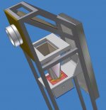
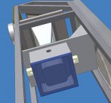
Here is another shot from a different angle. The condenser lens is mounted inside the end of the light pipe and the large passive heat sink is connected to a large aluminum arm which hold the heat glass and will also mount the light and reflector which are not yet shown. The thick LCD mounting plate will be ancored and adjustable with threaded screws (also not shown).
Hezz
Hezz
Attachments

nice stuff hezz, but i got 1 question for ya, do u know how to make square to rounds? i do if u need help, cos your pyramid is a square to round and unless u got experience in making them and access to a mig welder or a square to round press it cant be done.
Trev
Trev
Trev,
Ya that light pipe is going to be the hard part but I'm going to make it out of thinner aluminum. My feeling is that it will have to be treated like two circles with the length around the rectangle as the same as a larger circle with bend allowance added. Then I will just crease one end at the proper places. I'm sure the flange will have to be added seperately but I modeled it as one for design convenience.
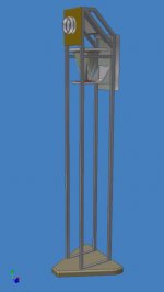
Here is a shot of the whole thing so far. The material covering the frame will only extent down far enough to cover the internals and the bottom will be left open for air flow. The top and angled top portion will be covered with some kind of mesh to let the whole thing act like a chimney. I will add one 120mm quiet fan if I have to to contain the heat but I'm trying to make this thing entirely passive to be silent.
If you know how to go from round to rectangular bend on sheet metal I will appreciate any help you have. Thanks so much, I think that is going to be the only thing more difficult with this design.
Hezz
Ya that light pipe is going to be the hard part but I'm going to make it out of thinner aluminum. My feeling is that it will have to be treated like two circles with the length around the rectangle as the same as a larger circle with bend allowance added. Then I will just crease one end at the proper places. I'm sure the flange will have to be added seperately but I modeled it as one for design convenience.
Here is a shot of the whole thing so far. The material covering the frame will only extent down far enough to cover the internals and the bottom will be left open for air flow. The top and angled top portion will be covered with some kind of mesh to let the whole thing act like a chimney. I will add one 120mm quiet fan if I have to to contain the heat but I'm trying to make this thing entirely passive to be silent.
If you know how to go from round to rectangular bend on sheet metal I will appreciate any help you have. Thanks so much, I think that is going to be the only thing more difficult with this design.
Hezz
Attachments
Guys,
Here are some more of my design ideas to make a silent fanless projector. You will see in this picture that the light is enclosed in a big aluminum box that is actually the reflector and a thermosyphon evaporator combined. The evaporator is connected to a condensor on the big heatsink (which is not shown).
Hezz
Attachments
- Status
- Not open for further replies.
- Home
- General Interest
- Everything Else
- The Moving Image
- DIY Projectors
- New High end 7" LCD projector design proposal