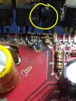
And the component 103J10D yellow rectangular piece in post 6 I need to know how to go about testing it as well please.
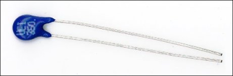
I was looking for metallic braid. The device with the braided fiberglass sleeving is a thermistor. They RARELY fail.
The 103J100 part is a capacitor. It's likely OK. You can change it if you don't like the way it looks but the burning is probably just superficial from the FET flame-up.
This page may help:
bcae1.com - Car Amplifier Repair Tutorial - The Basics
The 103J100 part is a capacitor. It's likely OK. You can change it if you don't like the way it looks but the burning is probably just superficial from the FET flame-up.
This page may help:
bcae1.com - Car Amplifier Repair Tutorial - The Basics
Last edited:
So that thermistor melting wouldn't harm it at all? Don't get me wrong I'm not questioning you but I'm more or less wondering how that is possible??? And no I'm not worried about the looks of the inside. As long as the capacitor is fine I'm not going to change it. Just wanted to make sure I had a good idea of what all to order. When I order the parts I would like to make sure I have everything I need to do this job all at once.
The thermistor was melted to the transistor when I took the hear sync off of them. It cracked apart when I popped them up off the insulator. It looks like it's damaged in my opinion but no the capacitor is fine it's just got a little carbon deposit.
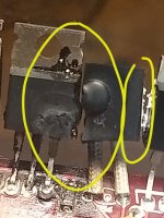
The thermistor was under the rubber pad. When you pulled the rubber off, did the thermistor break apart? The image below is an example of a thermistor.
The power supply FETs are the components that I saw that burned and crumbled.
Did you read the page I linked to?
The power supply FETs are the components that I saw that burned and crumbled.
Did you read the page I linked to?
Attachments
The rubber is nothing more than a space filler to allow the clamp to push the thermistor against the heatsink .
The drivers you where asking about are the following:
2SB647 2 Q25,Q26 PNP TO-92L
2SD667 2 Q24,Q27 NPN TO-92L
You should replace with same if available. There is a replacement we use but I don't have my notes handy and will check when I'm back in the office.
I've perused this thread, but will need study it further. Perry's advice is solid and I concur replacing parts unnecessarily adds time and expense.
To sum up for the time being, replace all mosfets, gate resistors, and drivers. Clean up the board as Perry suggests, remove any carbonized fiber glass that may have become conductive. Also, check for any shorted outputs.
Replace the drivers and Gate resistors(100 ohm?), but before replacing Mosfets (IRF3205 from same batch) I recommend you test for drive to the mosfet gate pads with an oscilloscope. If you don't have a scope a DC volt meter will do. Check the resistance across the outside mosfet pads (gate to source)before applying power. post any questions if my instruction is unclear. I'm pressed for time at the moment. I will check back later, but my not have definitive answers until I return to the office tomorrow.
The drivers you where asking about are the following:
2SB647 2 Q25,Q26 PNP TO-92L
2SD667 2 Q24,Q27 NPN TO-92L
You should replace with same if available. There is a replacement we use but I don't have my notes handy and will check when I'm back in the office.
I've perused this thread, but will need study it further. Perry's advice is solid and I concur replacing parts unnecessarily adds time and expense.
To sum up for the time being, replace all mosfets, gate resistors, and drivers. Clean up the board as Perry suggests, remove any carbonized fiber glass that may have become conductive. Also, check for any shorted outputs.
Replace the drivers and Gate resistors(100 ohm?), but before replacing Mosfets (IRF3205 from same batch) I recommend you test for drive to the mosfet gate pads with an oscilloscope. If you don't have a scope a DC volt meter will do. Check the resistance across the outside mosfet pads (gate to source)before applying power. post any questions if my instruction is unclear. I'm pressed for time at the moment. I will check back later, but my not have definitive answers until I return to the office tomorrow.
The resistances across across the outside mosfets pads(gate to source) with or without the mosfets in place should be 10K ohm, this is of course there are no solder bridges and the drivers have been replaced, and there is no conductivity due to carbonized fiberglass between the pads. If not you need to inspect the board and clean or remove solder bridges.
- Home
- General Interest
- Car Audio
- New here Kicker ZX 1000.1 help identify burnt transistors