The derivation for the TPC network makes the assumption that the input to the VAS is a virtual ground, and it seems like that's not true at lower frequencies where there isn't much feedback around the VAS.
You really need to check out that final "bonus" page of my paper 😉
Ah, very good. I've got a copy of the paper with the addendum and will look at it tomorrow. I really appreciate your dropping by to comment.
...It arrived today and I installed it.
...TBH, I don't like it. My immediate reaction was that it lost some detail. The Eizz uses carbon film resistors. It sounds exactly like what you read: not bad, a little warm and smooth. Everything is still there, but it's lost some sparkle...
...The damned thing is I can't hear a difference, short-term, when I swap back and forth with the Topping. But the subjective impression remains...
First consider that burn-in may be taking place. It is a real, audible effect which applies to most if not all electronics components to some degree or other. Some things take maybe running overnight to burn-in, other parts can take much longer to finally settle all the way (to your limits of audibility on your system, that is).
However, not quite clear on what the current status of perceived difference is. Do think a difference remains or not? If so, is there anything at all which is very specific that you can point to that is different? If not, either there is now no audible difference, or else you are fooling yourself about a difference.
Let me give you an example of what I mean by specific: In Alan Parson's recording, I Robot, around 2/3 or 3/4 of the way through the piece an instrumental sound almost like a pitched alarm clock starts to play. Don't know how the sound is produced, but under some playback conditions here it can sound like a hard mallet hitting on a metal bar located in a reverberant room, such as perhaps could be produced by a xylophone in certain recording studios. With a different component in the circuit the instrument sound might be more ambiguous, like maybe it is produced by a synth with a bit more of a smeared out sound on the stick attack portion.
One important thing when listening for such a difference is to check to find out if you can identify it blind. That may take some practice, so be patient. Your brain might have to do the equivalent of learning how to recognize the sound of a particular new word in a foreign language you have just started studying.
Other things to try include seeing if you can find someone else that can recognize the difference blind (say, after some training and practice).
Also, see if you can do it consistently over a few days. In such test trials as intended for learning it is okay with me to allow the listener to adjust the volume level as needed in order to find a comfortable level for accurate recognition (remember, too loud can be deafening, so be careful not to reduce your sensitivity accidently; sometimes quiet is better, sometimes mid-level, it depends), also it should be okay if the test is not strictly double blind. It should be effectively blind though, with no accidental cheating.
One possible error to know about and to try to avoid can occur when listening unblinded: If you know which DUT you are listening to, you might accidently listen for something different depending on which version of the sound you are expecting. For example, you may listen to HF parts of the specific sound if you think DUT #1 is in the circuit, and then listen to LF parts of the sound if you think DUT #2 is in the circuit. That is a mistake that can easily lead to fooling yourself. You must listen for the exact same thing regardless of which DUT you think might be in the circuit.
Other mistakes to avoid can be learned along the way. One thing I try to avoid is listening for a vaguely defined difference such as 'duller.' What exact sound at what point in which song is duller every time in what specific way? Can you recognize it blind? If the answers to those questions don't convince you there is a real effect, then assume at least for now there isn't a real difference. If you later find you can reliably learn to recognize a difference, then consider revising your prior opinion. Opinions don't have to be cast in concrete. You can and should consider revising them as relevant new information comes to light. Also, a possible opinion status could be 'undecided.' You don't have to force yourself to guess, nor to jump to conclusions.
I may take the thing apart and replace the resistors with metal films. I'm not sure it's worth the bother. It's possible I'm just fooling myself. Maddening hobby, this.
Suggest to give the thing some time to settle, burn-in, or whatever you want to call it. Could happen for a variety of reasons. Could be switch contacts cleaning themselves with use, doesn't necessarily have to be the resistors.
After that if you can learn to identify specific differences in specific sounds in specific pieces of music, then you are likely correct about an audible difference existing. More people learning to consistently hear the effect make it more likely to be something real. You being able to do it consistently over multiple days makes it more likely as well.
Last edited:
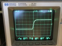
In response to a question Mark asked in another thread, I did some measurements on the HPA2 this morning. I already posted the square wave response here, but not with a parallel capacitor. Below is the output when driven by a 1V peak, 20 kHz square wave. The images are with a 50 Ohm load, and then with a 0.01uF and 0.1uF cap in parallel.
The latter is a huge capacitive load, so I guess the amplifier is immune to oscillation.
I measured the power output at clipping to be 1.6W into 50 Ohms, and 2.5W into 25 Ohms.
The latter is a huge capacitive load, so I guess the amplifier is immune to oscillation.
I measured the power output at clipping to be 1.6W into 50 Ohms, and 2.5W into 25 Ohms.
Attachments
Ringing may be associated with SQ issues, at least some people seem to think so. Haven't seen a complete justification for why such a correlation might exist. Do have some suspicions, nothing more.
Of possible interest: https://www.ti.com/lit/an/slyt630/s...66339&ref_url=https%3A%2F%2Fwww.google.com%2F
Of possible interest: https://www.ti.com/lit/an/slyt630/s...66339&ref_url=https%3A%2F%2Fwww.google.com%2F
Last edited:
I designed the amplifier for a target 60 degree phase margin. A capacitive load necessarily reduces the phase margin and causes ringing. Designing for more phase margin has its own drawbacks. What I show here goes way beyond the amount of capacitance you would see in real life and is not indicative of the behavior with a normal headphone load. The key is the amp didn't break out into oscillation.
There have been cases of power amps blowing all the output devices when someone used high capacitance speaker wire. Some designers tend to be cautious about what a user might do, other designers feel users shouldn't do unreasonable things. Of course some amplifiers are now built into speaker cabinets, in which case they can be optimized for that exact load. Just saying 🙂
Last edited:
I regret that so many build threads don't give much information about how the completed project sounds. That's why I've written about my listening impressions. It opens up a huge can of worms, though, and I want to back away from all that. I'm learning I'm not a reliable judge of sound quality.
After listening to the amplifier with the new attenuator for a couple of hours, it seems I was primed to expect a loss of detail and was probably fooling myself. I regret posting so quickly. The difference I thought I heard seems to be receding. I need to stick with it for a while and see how I feel long term. I have my own way of doing subjective evaluation that is in line with what you wrote to me personally. I'm still learning.
TBH, I don't trust anyone's subjective evaluations. Not professional reviewers and not award-winning amplifier designers. I'm still on the fence and will come to my own conclusions, at my own pace, according to my own agenda. Mostly, I just want to have a good time when I'm listening to my stereo. My amplifier sounds pretty good to me. It's enough for now and I will keep at the experimenting.
I said I wanted to take a break and it's because I don't want to drag this thread down into a subjectivist debate and my own navel-gazing. I'm not going into hiding, but I plan to stick more to technical things, and only when I have news to report.
There have been cases of power amps blowing all the output devices when someone used high capacitance speaker wire. Some designers tend to be cautious about what a user might do, other designers feel users shouldn't do unreasonable things. Of course some amplifiers are now built into speaker cabinets, in which case they can be optimized for that exact load. Just saying 🙂
I put an output inductor in there out of an abundance of caution. Most headphone amplifiers don't use them because headphone cables don't tend to be long, super high-capacitance monstrosities like some tweako speaker cables.
For a non-professional, pulling off a project like this is a huge undertaking and in the interest of not driving myself crazy, I didn't investigate every last thing. It's a real accomplishment, I think, that I got this amp built and that it turned out as good as it did.
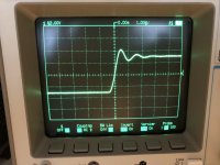
In the Solid State forum, Bob Cordell suggested I try my test with the ultrasonic input filter disabled. I posted some photos there. This is a brutal challenge to the amplifier. The result was mild overshoot, and somewhat increased ringing. No other misbehavior. Some minor compensation tweaks could probably improve it. With the filter bypassed, a square wave input is likely to overload the input stage, so that test should be interpreted with the proper perspective.
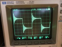
I tried the capacitive load test on the A30 Pro and observed mild overshoot and ringing, no worse than my amplifier, TBH.
Agree you have a nice looking project there that is unlikely to fail from oscillation. Congratulations on the achievement!
If you do go ahead with an HPA-1 project then after some time it would be good to know how you compare the sound of the two HPAs. Since I know what a stock HPA-1 sounds like to me, the comparison should help make it possible to have a better idea about the sound of your design. With a shared reference device maybe it is possible to make subjective comparisons more practical?
If you do go ahead with an HPA-1 project then after some time it would be good to know how you compare the sound of the two HPAs. Since I know what a stock HPA-1 sounds like to me, the comparison should help make it possible to have a better idea about the sound of your design. With a shared reference device maybe it is possible to make subjective comparisons more practical?
There's been more discussion in the Cordell thread on the Solid State forum about the ringing I observed. I did some playing in SPICE. This isn't oscillation and isn't related to the compensation scheme. It's an interaction between the output inductor and the huge cap I hung on the output. Without the inductor, the cap introduces a pole that cancels the zero in the TPC network and makes the amplifier oscillate. With the inductor, the amplifier is unconditionally stable, but can ring if the capacitor is large enough. For any reasonable value of load capacitance, say, 100pF, the 10 Ohm resistor across the inductor is enough to dampen out the ringing, says SPICE. In real life, the headphone cable will add series inductance of its own, though I have no idea how much.
Bottom line is this ringing is definitely not a sign the amplifier is unstable, can't be improved with compensation, and is unlikely to be of any consequence in real-world applications.
I confirmed in SPICE that the overshoot I saw with the ultrasonic input filter disabled is due to the front end overloading. It's normal, and that's why we have the filter in the first place. The fact the amplifier didn't go nuts without its filter is another positive sign.
@hpasternack -wonderful, thoughtful update. I'm still watching with interest.
For headphone cables, since the conductors are small dia, and the insulation thin, low-loss polyethylene or sim, and the pairs closely bound, -I can suggest (from some messing-about here for sim reasons!) that the headphone lead inductance can approach the notional 1uH /metre you might expect. I found, about 2.8uH for 2m of lead cut off a spare for my AKG 701s, if that helps. Something like that, give or take.
The motional impedance etc of a given pair of headphones you can approximate from the impedance plot; the very best source of these was Inner Fidelity, before Tyll Hertzens retired - now usefully defunct, but I found a link to a consolidated bundle of his measurements here:
https://www.stereophile.com/content/innerfidelity-headphone-measurements
: D
@hpasternack -wonderful, thoughtful update. I'm still watching with interest.
For headphone cables, since the conductors are small dia, and the insulation thin, low-loss polyethylene or sim, and the pairs closely bound, -I can suggest (from some messing-about here for sim reasons!) that the headphone lead inductance can approach the notional 1uH /metre you might expect. I found, about 2.8uH for 2m of lead cut off a spare for my AKG 701s, if that helps. Something like that, give or take.
The motional impedance etc of a given pair of headphones you can approximate from the impedance plot; the very best source of these was Inner Fidelity, before Tyll Hertzens retired - now usefully defunct, but I found a link to a consolidated bundle of his measurements here:
https://www.stereophile.com/content/innerfidelity-headphone-measurements
Cool, thanks. Off hand, the rising impedance curve doesn't look like it would be troublesome at all, which probably explains why headphone amplifiers don't typically have output coils. I understand that loudspeakers in general look inductive at higher frequencies. Makes sense since the voice coil is, well, a big inductor. IIRC, I measured my coils at about 1.2-1.4uH. So the cable inductance will be higher, according to your measurement.
Some people insist amplifier output coils degrade the sound. The best explanation I can find for that (if it's true) is that the coil either couples into adjacent circuitry, or magnetic materials within its field induce distortion. For that reason, I didn't wind my coil around a resistor, which used to be common practice but seems to be falling out of favor. The currents here are much lower than in a loudspeaker amplifier, so I guess the danger of magnetic saturation is lower. But I still kept the center clear and tried to place the coil away from sensitive circuitry.
The simulation goes into oscillation with a large capacitor on the output and no inductor. Another benefit to the coil is maybe it keeps RF out of the circuit, but for that purpose it might be better to put it right at the output jack. This blocks RF at the ingress and physically separates the coil from the active circuitry. The whole thing is probably unnecessary in practice, so who knows?
I did the square wave test on the Topping. It has a similar amount of overshoot to my test case with the HPA2 input filter bypassed. I just went into the A30 Pro RCA jacks and didn't try to bypass anything internally. I'm going to guess Topping leaves out or minimizes the input filter because it probably slightly degrades the noise performance, and of course introduces some HF rolloff and phase shift. IIRC, I saw something about this on the JDS Labs site. I'm extremely cynical about Topping and Audio Science Review. To get on top of Amir's chart, you need absolutely the best specifications. The filter adds series resistance and a bit of attenuation which will raise the noise figure a little. We can't have that, right?
The Topping also rings with a capacitor on the output, but doesn't oscillate. The ringing is similar in magnitude to what I measured on the HPA2. As far as I know, the Topping doesn't use an output inductor, but I could be wrong. If so, it's very impressive that it maintains its stability with such huge amounts of negative feedback and a big old capacitor in parallel with the load.
The 10 Ohm resistor in parallel with the coil adequately damps the LC resonance for realistic values of C. You can minimize the ringing in the simulation with large caps by making the resistor smaller, but this reduces the isolation provided by the coil. So you can either have ringing due to the coil itself, or ringing (and oscillation) due to the capacitor degrading the phase margin with the coil partially bypassed. Both cases are irrelevant in real life because the amp will never see such a load.
The op-amps used in the Topping have much wider bandwidth than my discrete output stage, which helps. It also has ten op-amps in parallel at the output and nested local feedback. So the open-loop output impedance is probably very low and, I imagine, keeps the pole due to the load capacitor at a high frequency where it's not so troublesome.
The main takeaway from the test, as I said before, is that my amplifier seems to be unconditionally stable, at least at the 3V peak signal level I used for testing.
Thanks for the link to headphone measurements. One thing caught my eye under the Beyerdynamic DT-880 (250 ohm) is the 90dB vs 100dB distortion. At very low frq it rises as expected due to displacement, and the 100dB level is correspondingly higher. However, moving right, the 2 plots then merge to about the same level, which makes no sense to me, unless something else in the system is actually causing the distortion.Cool, thanks. Off hand, the rising impedance curve doesn't look like it would be troublesome at all, which probably explains why headphone amplifiers don't typically have output coils. I understand that loudspeakers in general look inductive at higher frequencies. Makes sense since the voice coil is, well, a big inductor. IIRC, I measured my coils at about 1.2-1.4uH. So the cable inductance will be higher, according to your measurement.
Some people insist amplifier output coils degrade the sound. The best explanation I can find for that (if it's true) is that the coil either couples into adjacent circuitry, or magnetic materials within its field induce distortion. For that reason, I didn't wind my coil around a resistor, which used to be common practice but seems to be falling out of favor.
..
In designing my amp, I spent a lot of time tuning and playing around with NFB configurations, and generally found THD results to be highly sensitive to the electrical model of the bass resonance, which I attribute to the reduced ability of NFB to cope with phase-shifted loads.
Switching between a simple resistive load and a R+L + (L||C||R) load consistently gave lower, less realistic THD results with the pure resistance.
I didn't have a fool-proof method of determining the required LCR values, other than looking to see what would result in the same overall impedance. And the L and C values for the bass were extremely large.
The distortion graphs don't seem that strange to me. I don't know enough about dynamic drivers to say what causes the apparent noise floor in the plots. It's not electrical noise, evidently.
A reactive load impedance turns the load line elliptical. It changes the V-I relationship at the speaker terminals, increases the output device operating area, and raises power dissipation in the amplifier. It's no surprise the distortion goes up.
I was wrong about the loudspeaker equivalent capacitance being small. It corresponds to the moving mass of the driver and the air, and it's huge as you say. But it's in series with the voice coil inductance and resistance, so the amplifier doesn't see it at high frequencies. It definitely impacts amplifier distortion and frequency response, but not so much HF stability.
I met a very nice fellow on ASR. He's a chef, not an engineer, with a strong subjectivist bent. We got to chatting via PM and then email and I ended up sending him my HPA1 to try out. He received it yesterday and sent me his first impressions, (lightly edited):
NB: I didn't actually "voice" the amp, so whatever unique sonic qualities it may have are quite by accident.
He has an interest in offbeat discrete amps and does not like typical high-feedback designs. He seems very particular in his subjective tastes and listens to a lot of live music. I am always skeptical of any subjective review, but it's encouraging to get a positive reaction from a third party.
I'm not sure why he finds the mid bass to be light. Could be a bona-fide issue, or maybe he's just used to amplifiers that aren't as "tight" as this one. As I mentioned earlier, this is the HPA1 with the Baker clamps and traditional Miller (over)compensation.
I just noticed an interesting thread in the Solid State forum about someone else's project using essentially the same Cordell front end as my HPA2:
https://www.diyaudio.com/community/threads/vfa-front-end-the-bunnyphant.369957/
FWIW and YMMV.
I am listening to your amp. It took a minute to warm up and sound right. A bit compressed at first and the bass was light. But, it is starting to open up and sounds quite wonderful. [T]he SQ is really fantastic. I love the way it sounds. It is extremely fast and tactile. It is definitely a midrange amp, which would make sense in terms of how you voiced it based on you being a classical pianist. Piano sounds amazing, as do guitars and percussive instruments. Still deciding on the low end. I would like a bit more low end between 100-200hz. I just added 6db of bass at 130hz with a Q factor of 1.9. Much better. Vocals sound great. Henry, this amp is awesome.
Really digging this amp. So excited to have it here for a listen. I am using good cables with it. Audioquest power cord and Moon Audio Blue Dragon interconnects. Definitely clean enough and transparent enough to show differences in the chain. Bravo!
NB: I didn't actually "voice" the amp, so whatever unique sonic qualities it may have are quite by accident.
He has an interest in offbeat discrete amps and does not like typical high-feedback designs. He seems very particular in his subjective tastes and listens to a lot of live music. I am always skeptical of any subjective review, but it's encouraging to get a positive reaction from a third party.
I'm not sure why he finds the mid bass to be light. Could be a bona-fide issue, or maybe he's just used to amplifiers that aren't as "tight" as this one. As I mentioned earlier, this is the HPA1 with the Baker clamps and traditional Miller (over)compensation.
I just noticed an interesting thread in the Solid State forum about someone else's project using essentially the same Cordell front end as my HPA2:
https://www.diyaudio.com/community/threads/vfa-front-end-the-bunnyphant.369957/
FWIW and YMMV.
If the sound of the HPA-1 is a bit off from what it should be, probably reasonable to look first for any differences between the original version and the diy one. Different layout and or different component choices can have some effect.
Mark, I designed two amplifiers this year, which I named HPA1 and HPA2 for lack of a better idea. They are documented in this thread. In retrospect, this was a poor choice of names. I realized after the fact that there are already a couple of commercial products called "HPA1" or "HPA-1."
If I write "HPA1" it means my "Blameless" headphone amp, whereas "HPA-1" means the Pass design. This is confusing, but the hyphen is definitive.
I've started work on a version of Jeff Young's Pass Labs HPA-1. I have all the semiconductors now. Jeff's board is nice, but I have my own ideas. Designing a new amp takes time and energy, even starting from someone else's schematic. It will take me a while.
I have no idea what a real-life HPA-1 sounds like and I have no way to audition one. As you like to say, best to build it as designed before making changes. I realized, studying Jeff's work, that it's not a true clone. If I had authoritative design files for the HPA-1, I would build it as close to spec as possible. Jeff did a great job of reverse engineering. But I don't know how realistic it is to call his design an "HPA-1." I'm thinking of it as a new amplifier in the style of Pass Labs and heavily inspired by the HPA-1.
Henry (May I call you Henry?), I've really enjoyed reading about your design and development here! May I propose that it be named something that uniquely identifies and credits you, such as "BlameHenry-2021" or "HPA-HPAsternack2021" rather than yet another HPA or other...?
Thanks again for your thoughts!
Thanks again for your thoughts!
- Home
- Amplifiers
- Headphone Systems
- New Headphone Amplifier Design