A couple things to mention. The schematic shown is purposefully misdrawn. Be careful as the loaded output transformer will reflect nearly full B+ voltage on it's primary windings!!!! I can see why Steve had to completely enclose the transformer. It is a liability issue.
The secondary is what is wired in series with the driver and provides inductance, not the OPT primary. Interwinding capacitance restores high frequency response in comparison to the typical inductor. The amount of midrange can be controlled by the load resistor placed across the primary. On my vintage 12K / 6R OPT it can be from 100K to 500K depending on how much midrange is desired. Running an open unloaded primary winding increases core saturation and distortion.
I will post pictures later if anyone is interested.
Last edited:
A couple things to mention. The schematic shown is purposefully misdrawn. Be careful as the loaded output transformer will reflect nearly full B+ voltage on it's primary windings!!!! I can see why Steve had to completely enclose the transformer. It is a liability issue.
The secondary is what is wired in series with the driver and provides inductance, not the OPT primary. Interwinding capacitance restores high frequency response in comparison to the typical inductor. The amount of midrange can be controlled by the load resistor placed across the primary. On my vintage 12K / 6R OPT it can be from 100K to 500K depending on how much midrange is desired. Running an open unloaded primary winding increases core saturation and distortion.
I will post pictures later if anyone is interested.
I'd love pics. Thanks!
A demonstration video is being loaded to Youtube so you can hear how well this actually works. I will post a link here when it is finished uploading.
I have tried several different output transformers and each has a different effect on sound. Inductance and interwinding capacitance has a large effect on the frequency response. So far the little 12K/4R Telefunkens shown in the video sound the best.
nice work greenvalve!
I have bunch of output transformers on the shelves, I might give it a try
do you have a way to measure the fr response?
ed
I have bunch of output transformers on the shelves, I might give it a try
do you have a way to measure the fr response?
ed
second question, if the full range has big ripples in the upper frequency response
and you adjust amount of the midrange, does it do something to the ripples?
in other words, does it become smoother? like the response in decwares graph
and you adjust amount of the midrange, does it do something to the ripples?
in other words, does it become smoother? like the response in decwares graph
The high frequency is only slightly controlled by the loading resistor. It will be very dependent upon the winding capacitance of the output transformer. However, if you use an output transformer with more inductance and less capacitance you could use all sorts of components on the primary to control frequency response. I sort of like the simple synergy of just the resistive load and no added capacitance.
So far the little 12K/4R Telefunkens shown in the video sound the best.
🙂
The ones i was going to play with are also TFK 12k/4R
dave
🙂
The ones i was going to play with are also TFK 12k/4R
dave
You are really gonna like this Dave. I have only been listening for a few hours, but so far I would say it does a better job than 24/96 digital only domain EQ, and much better than the typical baffle step style passive. I am using the baffle-less speakers as shown in the video and there is plenty of fast, deep, real, bass. I will take a pink noise FR measurement soon.
Last edited:
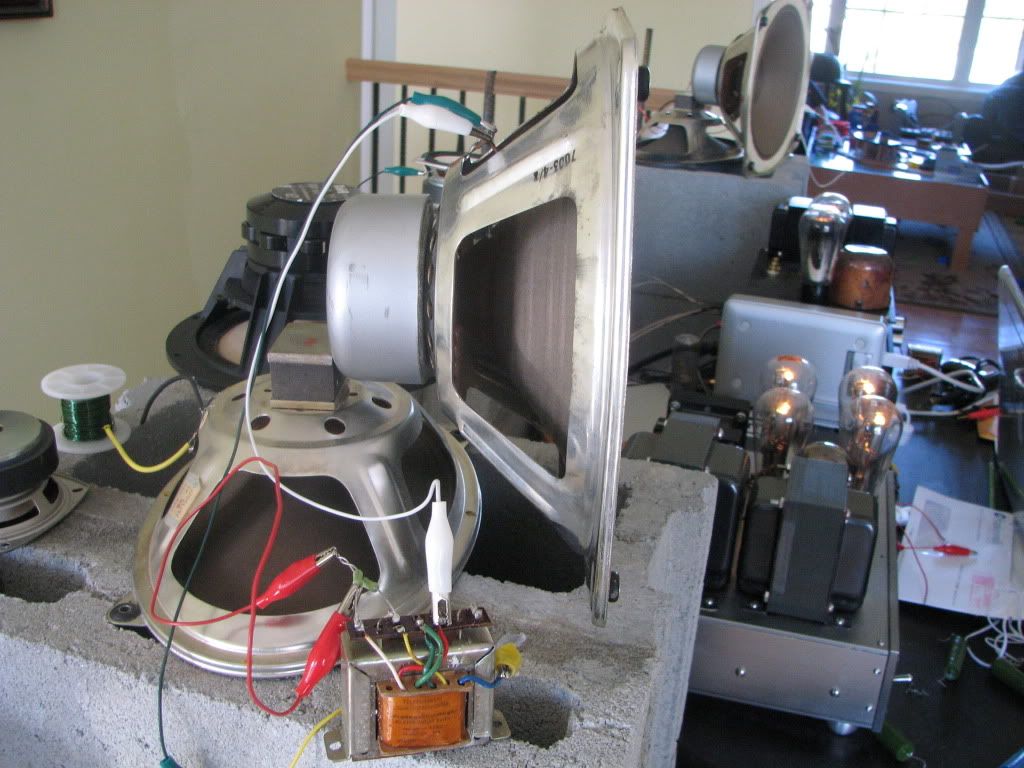
Greenvalve,
are those the tang band 1808's in the back of that photo? if so, have your tried any experiments with them? I've been eyeing the 1808's.
are those the tang band 1808's in the back of that photo? if so, have your tried any experiments with them? I've been eyeing the 1808's.
Hi Eric,
The Tang bands proved to be a disappointment to me. Slow and lacking in detail at low volume, in comparison to vintage light coned drivers like the Grundigs you saw in the video.
As far as using an OPT as an inductive load in series with a driver... there is ringing or perhaps core saturation. This manifests itself as distortion of transients. Using a driver that is well damped, such as Steves modified driver, it is difficult to hear. But listening to a few of his audio sample tracks I did hear it. The distortion is very audible on light coned drivers with compliant suspensions.
Thanks, thats good to know. I have a pair of the smaller 4 inch TB W4s, in a box, and was happy with them, but haven't heard the 1808s yet.
very interesting video greenvalve. i don't quite get how do you obtain such response from baffle less FR? how much boost is the low end receiving?
also the high quality recording on the decware site are interesting and seen trough an hi-res spectrum equilizer show a good exstension from the driver output:
wondering if such an hi-quality recording of pink noise would be representative of driver frequency response
also the high quality recording on the decware site are interesting and seen trough an hi-res spectrum equilizer show a good exstension from the driver output:
wondering if such an hi-quality recording of pink noise would be representative of driver frequency response
Hi Eric,
The Tang bands proved to be a disappointment to me. Slow and lacking in detail at low volume, in comparison to vintage light coned drivers like the Grundigs you saw in the video.
As far as using an OPT as an inductive load in series with a driver... there is ringing or perhaps core saturation. This manifests itself as distortion of transients. Using a driver that is well damped, such as Steves modified driver, it is difficult to hear. But listening to a few of his audio sample tracks I did hear it. The distortion is very audible on light coned drivers with compliant suspensions.
Bummer. I have Planet 10 modded 1808's for my ZOBs.
Perhaps the ringing is cause by the capacitance of the iron, so a lower value primary as well as a higher resistance might help reduce or eliminate the ringing? Or a larger frame if it's core saturation? I haven't ordered my iron yet so I'm still not sure what value I'll order.
In reply to Bears' PM I will try to clarify what is going on here, for the benefit of others.
The output transformer secondary is wired in series with the speaker (Its 4ohm 6ohm 8ohm etc side). The OPT primary (12K or 9K8, etc) has the most inductance when it is open / without any connection. It sounds "thin" when the primary is shorted out, providing no inductance. You can add a resistive load across the primary to control the amount of inductance that the OPT reflects (more midrange). For more high frequency you could also use a capacitor across the primary if the OPT interwinding capacitance is low. Its value will be very tiny, as even a small amount of capacitance has a large effect.
But there are issues. Just like the PI filter of a B+ power supply ringing can occur when two chokes with winding capacitance are placed in series. If the distortion becomes audible depends upon the specific transformers used. Also the core of the OPT may saturate when low frequency / high current flows, creating distortion.
The end result will depend upon the synergy of the amplifier output transformer, the filter transformer in series with the speaker and the inductance of the speaker itself.
The video has no bass boost or EQ other than the use of the series wired output transformer.
Last edited:
I have done some simple tests yesterday, with small SE output transformer, from Magnavox EL84 amp. Its probably 3k primary, 4 ohm output. I used pair of small 4" fullrange for tests. One was driven directly, the other as described above, secondary in series with the speaker, primary on 5k pot. No capacitors in experiments.
Simple left-right speaker comparison was done. First, it works. Kind of. It seems to me its working as shelving filter. I have done no fr response measurements, but may do later. However, I must say, I did not particularly liked the decrease in sensitivity, and it sounded as a decrease in dynamics. You can dial in whatever the balance you like, but in general, sound suffers. Well, it depends on the quality of output trafo used, I used very small one, I admit.
It probably takes a lot of experimentation to get perfect result.
Still, one thing I do not understand, how can it flatten out fr response?
I will do some measurements later.
ed
Still, one thing I do not understand, how can it flatten out fr response?
I will do some measurements later.
ed
I believe the trafo "absorbes" the energy storage (the two peaks in the dayton driver), about the rest of the flattening effect it may be due to the mechanical size of Decware baffles and the resonator below.
Decware is using a PR (passive radiator)?
Anyone put a cap on that primary (the non speaker side).
The other thing is that the DCR is in series with the driver reducing the Qt... good to not forget.
I have no clue how he gets a response THAT smooth... it's almost impossible given the "raw" curve. Even EQ'd to the max, it is impossible to get the peaks to smooth out so much. So, how that is being accomplished is a mystery that will have to remain until someone BUYS one and does a real world test and puts it up here...
_-_-bear
Adason, you may want to try this with as big transformer as you can find. With the small transformer, there's distortion on the higher volumes. On the other had, I agree that you can dial-in the balance you like, but something gets lost along the way, the sound becomes less "dynamic" and there's a feeling that it also shelves some frequencies that you might not want to be shelved down, so it just sounds different, since some sparkle is lost...
I am suspecting that its not just a simple transformer with resistor or capacitor. There must be something more then what Steve is sharing on his web. If it is that simple, he wouldnt share and we wouldnt be discussing it here. where are the electrical engineers on this forum? 🙂
creek
creek
- Status
- Not open for further replies.
- Home
- Loudspeakers
- Full Range
- New FRX OB driver from Decware