Hi Tom,Just a data point: I build an FDNR as shown in Post #5 using an OPA1612. It worked great in the simulator but the opamp lost its mind in reality. It didn't even land at the right DC op point! I put in an LME49860 instead at the circuit worked as designed. Go figure.
All opamps came direct from TI (or via Mouser) and I did try a second OPA1612 just in case. I never figured out why it wouldn't work but I also didn't dedicate much time to figuring out why.
Tom
I’m using this #5 topology in my Riaa preamp to simulate a coil in an LC rumble high pass filter to get 12dB/oct, 6dB/oct or no rumble filter at all but still active as a DC blocker at <1Hz high pass.
I had to add two 10pF caps on both LM4562 opamps from output to - input to get it stable.
Works without any hickup also with the various fet opamps that I tried.
Hans
As I pointed out in Post #9, the circuit in Post #5 worked fine for me with the LME49860 (and LM4562/LME49720 for that matter). I don't recall having to use compensation capacitors to make it stable, but I might have added 10-22 pF. I certainly had footprints on the board for that.
Tom
Tom
For what it's worth, I calculated the characteristic polynomial for the circuit of post #1/post #12 for op-amps that behave as voltage-controlled voltage sources that integrate to time, and found that the polynomial always becomes Hurwitz when the gain-bandwidth product of the op-amps is made large enough. This confirms what Mark wrote, but I still don't really understand why.
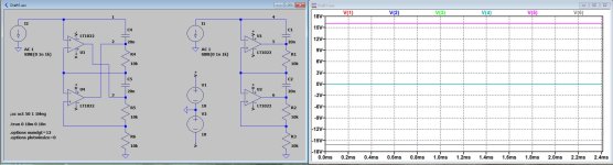
I've simulated the DC behavior in LTSpice for the circuits in #1 and #5, both drawn with the same opamp orientation just for easier visibility of the differences.
With the usual topology of #5 output is 0 Volt and both opamp outputs are at 0 Volt, resp point 1, 2 and 3.
However with the #1 topology, while the output is also 0 Volt, opamps are resp. latched up at +16Volt and -16Volt, resp points 4, 5 and 6.
So yes, #1 is stable in is latched up status, but completely unusable as a FNDR IMO.
Hans
Attachments
This doesn't say much for a circuit with multiple DC bias points. The simulator randomly converges to one of the DC bias points, and doesn't tell you if there are any others and whether those are stable.
Isn’t this single possible bias point with latched up opamps not enough to reject this circuit ?
Maybe It could be forced to latch up the opamps into one of four options like + + / + - / - - or - + where + and - are the latch up voltages, but that doesn’t make the topology more attractive, does it?
Just my two cents.
Hans
Maybe It could be forced to latch up the opamps into one of four options like + + / + - / - - or - + where + and - are the latch up voltages, but that doesn’t make the topology more attractive, does it?
Just my two cents.
Hans
Of course, but that's been clear for quite some time, see the last part of post #6 (the first part is incorrect) and see post #11.
What fascinates me is that a circuit with only positive feedback for DC, with a loop gain far above unity and with poles can still be small-signal stable according to Mark's measurements and my calculations. I don't see any particular advantage (and two obvious disadvantages, namely the two undesired bias points) compared to the conventional circuit, but that doesn't make it less fascinating to me.
If you should want to mimic this in simulation, you could put ic=0 statements on all capacitors and run a transient analysis with a small excitation. The circuit theoretically requires a resistor and a damping capacitor from Mark's node5 (your node 4) to ground.
Last edited:
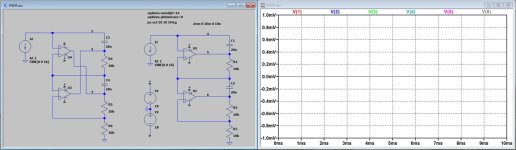
When I change the LT1022 for the single pole UniversalOpAmp2, with a 10Mhz GBW, everything changes and the FNDR becomes stable with both op-amps output's now at 0 Volt.
This 0 Volt stability stays when I add 50nV/rtHz voltage noise and 10pA/rtHz current noise and 1mV offset, worse as the LT1022 specs.
There is no way I can get it into a latched situation.
Very weird.
Hans
This 0 Volt stability stays when I add 50nV/rtHz voltage noise and 10pA/rtHz current noise and 1mV offset, worse as the LT1022 specs.
There is no way I can get it into a latched situation.
Very weird.
Hans
Attachments

Does the UniversalOpAmp2 include clipping and if so, have you tried a transient run with big enough signals to drive the op-amps into clipping?
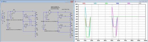
Here you are, first at 1msec the usual FNDR and at 5msec the special FNDR both short before clipping at -18Volt.
Second image is again with somewhat larger transients for the special version only, that now hard clips at -18 Volt.
Hans
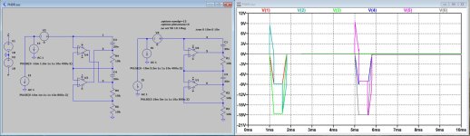
Second image is again with somewhat larger transients for the special version only, that now hard clips at -18 Volt.
Hans
Attachments
Due to the missing resistor at your node 4, Mark's node5, there is complete negative feedback through your C1, Mark's C3, around the upper op-amp at any frequency. Does that make any difference?
By the way, this is my calculation for the case with finite gain-bandwidth products. I hope I didn't make any mistakes. At least the dimensions of all terms are consistent, but that doesn't say anything about sign errors, factors of two and such.


I think it is possible to gain some insight into the dynamic stability by slightly redrawing the circuit:
 The top and bottom sections are now clearly separated and are connected at the "X" point. Both sections create a synthetic impedance on either side of X. For example, the bottom part presents a negative capacitance to the upper part; this capacitance is not stable by itself, but it becomes stable when loaded by the other section, and it also stabilizes it.
The same happens in the opposite direction, but the upper circuit is now a negative inductance.
They complement each other, and the resulting global circuit becomes stable.
If one of the section is replaced by a spice negative component (C6), the behaviour remains identical.
The circuit could be compared to a bicycle: a motion-less bicycle has two stable states: lying on the ground on its left side or on its right side (= positive or negative latchup). When the bicycle is moving (=linear range of opamps), a third (precariously) stable state emerges and the bicycle stays upright. However, if it crashes (=latchup), it cannot recover by itself.
To prevent such a crash, training wheels (antiparallel LEDs) can be added, forcing the circuit to remain within its linear range all the time

Placing a 3k9 resistor turns both versions into perfect oscillators.Due to the missing resistor at your node 4, Mark's node5, there is complete negative feedback through your C1, Mark's C3, around the upper op-amp at any frequency. Does that make any difference?
I didn’t have the time to further investigate, will have to wait until tonight.
@mark, what exactly was the circuit you used to stimulate the FNDR ?
Hans
3k9 from a low impedance oscillator. As I've already stated the Q was limited by the opamp performance, though I didn't measure it. A working FDNR in the standard circuits shouldn't be able to oscillate anyway as its emulating something passive. It can certainly resonate though.
It was a rather fruitless exercise simulating the FNDR as a separate unit because results were totally unpredictable.
That's why I made a third order 1Khz T filter, think of two Coils with a Cap in between terminated by a Resistance.
Since the FNDR represents 1/s²C, when used instead of the Cap, the two Coils can be replaced by Resistors and the termination resistance has to become a Cap.
I used the original LT1022 that Mark suggested, I only interchanged the FNDR's 20n cap in the middle and the 10K at the bottom, resulting in a smoother frequency response above 100Khz.
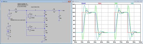
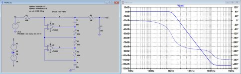
Now with this third order filter, I can relatively simple stimulate the circuit with a voltage source and watch the response.
When applying a 10V input pulse the various signals are shown in the first image below.
The FR is shown in the second image.
Even when at start up one of the LT1022 was latched up, directly after applying the first pulse it came out of latch up and performed further as shown in the image.
So it is still a FNDR version with a handicap, but when it finally works it keeps working, at least in my simulation.
Hans
That's why I made a third order 1Khz T filter, think of two Coils with a Cap in between terminated by a Resistance.
Since the FNDR represents 1/s²C, when used instead of the Cap, the two Coils can be replaced by Resistors and the termination resistance has to become a Cap.
I used the original LT1022 that Mark suggested, I only interchanged the FNDR's 20n cap in the middle and the 10K at the bottom, resulting in a smoother frequency response above 100Khz.
Now with this third order filter, I can relatively simple stimulate the circuit with a voltage source and watch the response.
When applying a 10V input pulse the various signals are shown in the first image below.
The FR is shown in the second image.
Even when at start up one of the LT1022 was latched up, directly after applying the first pulse it came out of latch up and performed further as shown in the image.
So it is still a FNDR version with a handicap, but when it finally works it keeps working, at least in my simulation.
Hans
Attachments
This particular implementation may or may not be useful (after all, classical alternatives exists, and mostly, they do not have unpleasant quirks), but the underlying principle opens up new perspectives: it shows that it is possible to associate circuits that are bonkers on their own but perfectly usable when associated in the right way.
This principle could be used to create useful chimera's, unrealizable in any other way. Impossible circuits made possible, a trip through the looking glass: I like that
This principle could be used to create useful chimera's, unrealizable in any other way. Impossible circuits made possible, a trip through the looking glass: I like that
Like this in fact: https://www.diyaudio.com/community/threads/nic-opamp-vas-topology.348646/
you can change resistance values in such an amp so the open-loop DC phase flips 180 degrees (the DC gain is effectively infinite too at the flip-point), but the closed-loop stability is basically unaffected... Closing a feedback loop can turn stable open-loop systems to unstable ones - which is a well known pitfall, but you can also use a feedback loop to change an unstable open-loop system into a stable closed-loop system - less well known in electronics (but obvious if you think about control systems more generally, such as steering a boat)
you can change resistance values in such an amp so the open-loop DC phase flips 180 degrees (the DC gain is effectively infinite too at the flip-point), but the closed-loop stability is basically unaffected... Closing a feedback loop can turn stable open-loop systems to unstable ones - which is a well known pitfall, but you can also use a feedback loop to change an unstable open-loop system into a stable closed-loop system - less well known in electronics (but obvious if you think about control systems more generally, such as steering a boat)
- Home
- Source & Line
- Analog Line Level
- New FDNR topology? Spot the flaw in its behaviour