I have seen some IEC power cords that were mis-wired by the manufacturer
Well, that's a disturbing thought. Everything on your checklist I got. Thanks.
I believe the original Dyna ST35, and the Dynaco FM-3 both had 2-wire power cords.
If possible, the ST35 should use a 3-wire power mains, and 3-wire IEC power cords, and 3-wire IEC input socket
Correct. New version will use a heavy 3-wire UL-listed power cord but not a socket. The 3-wire cord will run inside the chassis as shown in the diagrams I drew.
CD player with a 2-wire cord, or a turntable with a 2-wire cord, you may also have less hum (try both rotations of the 2-wire plug in the mains outlet).
I have had so many people argue with me about this over the years! It does make a difference in my opinion, even if it's not audible hum. When I replace a piece of 2-wire equipment, I test and then permanently label which way the plug should be oriented so when I unplug it I can plug it back in without testing again.
The drawing in post 101 is how I wound up grounding the RCA jacks I'm my ST35 build. It was quieter than just grounding to the chassis like the RCA jacks were grounded in the original ST35.
101 was close. Thanks to everyone who has contributed additional tips and tricks. This is where we are now. Additional suggestions and error corrections are always welcome!
Last edited:
Sometimes the solution is a completely separate ground wire run between the various elements of a system.👍
The transformer center-tap (red/ yellow) should go directly to the filter cap minus terminal - if it doesn't reach, splice some extra wire onto it. Otherwise ripple current will create a voltage drop on your ground bus and a hum you can't seem to fix... While you're at it, twist that wire with the red AC wires for magnetic field cancellation.
Done, and thanks!
The piece of bare copper wire that will serve as the attachent point for all of the wires will be approximately 2-1/4" long. Does it matter in what order the various leads I have illustrated are attached? As recommened above, I have drawn the center tap lead directly to the cap minus terminal. I have redrawn the common connection wire as a straight piece since it looks like it will work fine that way, and then I wondered about the order of the connections to it.
Last edited:
As Tom Bavis mentioned, mains hot/line/black should go to A terminal on the fuse holder. You can experiment with whether or not to chassis ground the input jacks; best choice is system dependent. There's a loop between interconnecting cables' signal returns with any common ground source, so the difference is the size of the loops.
All good fortune,
Chris
All good fortune,
Chris
mains hot/line/black should go to A terminal on the fuse holder.
Then the diagram provided with the kit is wrong:
Sometimes, a 3-wire power mains, a 3-wire power strip, and 3 wire cords to the various signal sources and power amplifiers can solve some ground loop hum.
Do that instead of using different power mains outlets for each equipment.
And, you can turn the whole system on and off, until the power strip wears out (and replace the power strip).
Note: Ground and Neutral are only the same thing all the way back to the Power Mains Switch/Breaker panel.
All other points along ground and neutral will be some milliVolts or even Volts different.
If anyone wants to read more about grounding, I found this helpful:
https://web.archive.org/web/20070104184532/https://www.aikenamps.com/StarGround.html
https://web.archive.org/web/20070104184532/https://www.aikenamps.com/StarGround.html
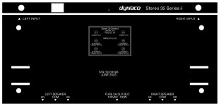
After several weeks of work, the chassis is almost finished, including painting the transformer screws black. The top is finished. All I have left to do is clearcoat the decals on the bottom. After a few coats of clear with wet sanding between, the decal edges are not visible any longer, and the decals are fully protected for life.
The whole amplifier is satin black. I fabricated the outputs with fiberglass board and spaced the binding posts correctly for double banana plugs. I also filled the screw holes on either side of the isolated input jacks, again backed by fiberglass board. The holes are no longer visible. The time spent adding the power switch on the front was well worth it I think. I have a decal for the triple cap, but I'm just going to tuck a piece of paper with the date and values inside the can instead.


Anyone have any suggestions on the wiring diagram and layout below before I go any further? I do think the fuse wiring was backwards in the directions.

The whole amplifier is satin black. I fabricated the outputs with fiberglass board and spaced the binding posts correctly for double banana plugs. I also filled the screw holes on either side of the isolated input jacks, again backed by fiberglass board. The holes are no longer visible. The time spent adding the power switch on the front was well worth it I think. I have a decal for the triple cap, but I'm just going to tuck a piece of paper with the date and values inside the can instead.
Anyone have any suggestions on the wiring diagram and layout below before I go any further? I do think the fuse wiring was backwards in the directions.
Attachments
Last edited by a moderator:

Why are the two power supply diodes pictured hanging out in the air in the assembly diagram below? Do they get hot?

So far so good with the chassis assembly. Hardware is not included with the choke. 🙁 That required two trips to the hardware store for bolts, nuts, lock washers, and a rubber grommet. 😡 I discovered that the bias adjustment board that sits in front of the power transformer grounds to the chassis through five different circuit board traces that connect through the mounting screws and metal standoffs, in addition to its own ground wire. So, I had to order insulating standoffs, which will leave the bias board ground running only to the central circuit grounding point. The rubber bushings and dual nuts included with the power transformer are almost impossible to install because there isn't room to tighten the lock nuts against the mounting nuts. Solution: another trip to the hardware store for nylon insert lock nuts. Those can be snubbed up against the mounting nuts without overtightening the mounting screws on the rubber bushings. The capacitor can is removable, which may come in handy some day if inspecting the caps becomes necessary. A layer of black felt wrapped around the three 120uF 450V capacitors stuffed inside the can provides a snug friction fit. The can just slips over them.

I am glad this isn't my first tube amplifier build because if it were, the number of wires might be overhwelming, especially packed into such a compact chassis.
I haven't stuffed the three PC boards yet. I guess that's next.
Any final comments or concerns on the planned wiring and routing?


So far so good with the chassis assembly. Hardware is not included with the choke. 🙁 That required two trips to the hardware store for bolts, nuts, lock washers, and a rubber grommet. 😡 I discovered that the bias adjustment board that sits in front of the power transformer grounds to the chassis through five different circuit board traces that connect through the mounting screws and metal standoffs, in addition to its own ground wire. So, I had to order insulating standoffs, which will leave the bias board ground running only to the central circuit grounding point. The rubber bushings and dual nuts included with the power transformer are almost impossible to install because there isn't room to tighten the lock nuts against the mounting nuts. Solution: another trip to the hardware store for nylon insert lock nuts. Those can be snubbed up against the mounting nuts without overtightening the mounting screws on the rubber bushings. The capacitor can is removable, which may come in handy some day if inspecting the caps becomes necessary. A layer of black felt wrapped around the three 120uF 450V capacitors stuffed inside the can provides a snug friction fit. The can just slips over them.
I am glad this isn't my first tube amplifier build because if it were, the number of wires might be overhwelming, especially packed into such a compact chassis.
I haven't stuffed the three PC boards yet. I guess that's next.
Any final comments or concerns on the planned wiring and routing?
Last edited:
The written directions do not distinguish between these two possible wiring configurations for the heaters.
V4, V5, and V6 are wired as shown in the actual schematic.
V1 is "crisscrossed" to V2 and V3, a situation that the written directions would allow.
Would this be a problem? I intend to follow the schematic as I assume it is correct but wonder what issues the "crisscross" heater wiring might create, if any?
Also, is it "best practice" to wire the heaters for the driver tubes at the end of the string as designed? The Chinese amplifier kit that I built has a separate winding for the driver tubes.
Last edited:
V1's heaters don't have a polarity (actually, none of them do) so can be connected however is convenient. You could consider biasing the heater center taps up to output valve cathode DC voltage (maybe +15VDC) by connecting the 100R/100R CT to output valve's cathode circuit. Or even adding a voltage divider from B+ to bias them up to maybe +50VDC.
But there are always some slightly better ways to do everything and we can't let the perfect be the enemy of the good. Striving for perfection in details causes bloat, and that would run against the Dynaco beauty of elegant simplicity, and with rapidly decreasing return for effort. (Put effort into speakers IMO).
All good fortune with your project,
Chris
V1's heaters don't have a polarity (actually, none of them do) so can be connected however is convenient.
That's good to know. I'm still very much a novice and learning new things every day. With AC power flowing one way in the driver stage heaters and the other way in the driver stage heaters, especially if "reversed" in one channel only, I wondered if it might cause some sort of unexpected noise problem.
and that would run against the Dynaco beauty of elegant simplicity
I passed that stage a long time ago in this project. 😉 Thus the "Series ii" plainly on the front of the amplifier.
A box of parts from Mouser arrived today. Maybe I can get some more done tonight. Still finishing the physical adssembly and final clearcoats on the bottom decals.
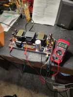
My spaghetti bowl of wires actually plays music - finally! 😎
If there is anyone in NE Florida - Central Florida - SE Georgia - or possibly western North Carolina - who is willing to test this amplifier and two others on an oscilloscope, please let me know. I'll drive them to you one afternoon for testing. It would be nice to see some actual measurements as-built.
All of the modifications result in a very tightly packed chassis.
It runs hot, but we all knew that. My cheap temperature probe measures ~125F on the power transformer and the power tubes are roasting like a burning fireplace. Still, it's not as hot as the four EL34's in my Dynaco ST-70 series ii (made by Panor corp circa 1991). I can't imagine running this amp with the tube cage on, but I bought one just in case a future owner wants it.


It's too early to judge sound quality as the tubes only have a few hours on them so far. I'm not very confident in the JJ driver tubes, but they weren't expensive.
I do not like the sockets as they have a death grip on the tubes that might very well break a circuit board, but it's too late now.
If there is anyone in NE Florida - Central Florida - SE Georgia - or possibly western North Carolina - who is willing to test this amplifier and two others on an oscilloscope, please let me know. I'll drive them to you one afternoon for testing. It would be nice to see some actual measurements as-built.
All of the modifications result in a very tightly packed chassis.
- All resistors are Dale (mostly 25ppm) and were tested to within 0.2% of specified value
- Cathode bypass caps are Nichicon Muse audio-grade electrolytic, tested within 0.5% of specified value
- Input caps are Wima
- Coupling caps are matched Cornell Dubilier polyproplyene (they no longer come with the kit, some small yellow generic cap does)
- Custom triple filter cap is 120uF x 3 @450V, stuffed in a cleaned out removable can not grounded to chassis
- "Virtual center tap" for heaters
- Power supply choke
- Bias board upgrade allows individual tube bias adjustment for each of the four output tubes
- Insulated gold input jacks
- Star grounding (requires insulated input jacks, insulated filter cap, insulated standoffs for bias board, insulated virtual center taps)
- CL-90 inrush current limiter
- Front-panel power switch
- Micalex tube sockets (included with kit)
- Custom binding posts spaced for dual banana plugs
- Upgraded power diodes
- Upgraded power cord
- Point-to-point wiring on both circuit boards (directly overlaid on PCB traces)
- Silver solder on all audio connections
- All-black satin paint scheme with custom decals (yes I painted every single visible screw and nut including those on the transformers)
- Matched and balanced JJ 12DW7 driver tubes (yes even though they are dissimilar triodes they are matched left-right on both sections)
- 6P14P-ER (10,000 hr rating) Soviet-era military output tubes
It runs hot, but we all knew that. My cheap temperature probe measures ~125F on the power transformer and the power tubes are roasting like a burning fireplace. Still, it's not as hot as the four EL34's in my Dynaco ST-70 series ii (made by Panor corp circa 1991). I can't imagine running this amp with the tube cage on, but I bought one just in case a future owner wants it.
It's too early to judge sound quality as the tubes only have a few hours on them so far. I'm not very confident in the JJ driver tubes, but they weren't expensive.
I do not like the sockets as they have a death grip on the tubes that might very well break a circuit board, but it's too late now.
Attachments
Last edited:
Nice work! It looks great.
I added the choke, bias board, CL-90, better RCA Jacks, etc. to mine also. It's one of my favorite amps to listen too. Recently I bought a couple quads of the Russian 6P14P-P's to play around with in several other amplifiers I built.
A modified Magnavox 9303 console amp and a single ended scratch build.
I like how they sound. I plan on getting a quad of the 6P14P-EV's, or ER's for my ST-35. I have matched JJ drivers and Sovtek EL84M's installed right now.
I was going to replace those yellow Illinois film caps also, but they sound fine to me personally, and I've used them in other amp builds.
Attachments

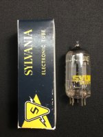
Are the JJ drivers ECC832? JJ lists them as equivalent to the 12DW7 / 7247
- Matched and balanced JJ 12DW7 driver tubes (yes even though they are dissimilar triodes they are matched left-right on both sections)
In my ST35 clone, NOS 7247's not only looked very different internally, they produced hum in both channels compared to the '832's, which are dead quiet.
Some day I will look into why the sonic difference... but it's far down on the list of projects
Jim
Attachments
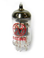
Are the JJ drivers ECC832? JJ lists them as equivalent to the 12DW7
ECC832 custom matched. Zero hum (92 dB speakers, ear directly on the speakers). I have had very bad sonic experiences with JJ tubes in the past and have actually thrown their tubes in the trash, but I'm willing to give these a try.
I have some ground gremlins with one of my three DACs, but that one is ready for the trash can anyway. Interesting that the ST-35 has a problem with it but my Chinese tube amp kit build does not. Like I said, that DAC is headed for the trash anyway. Others are fine.
I put a broken-in quad of standard Russian 6P14P in very briefly for testing and much preferred their sound over the 6P14P-ER, but the 6P14P-ER only have a few hours. I question the ability of the standard 6P14P to stand up to the abuse. If they do (and I will test) they are easier to get. The ER is available, but not in huge quantity. Given their 10,000 hr rated life, I think 200-300 hr break in is fair before judging them.
I was sort of in disbelief when I turned the amp on and it actually worked the first time. With all of the mods it's a heck of a wiring job to do it neatly and keep track of it all. That's why I spent so much time drawing that detailed color-coded wiring picture exactly to scale. It all went together exactly as planned, and it actually worked. I have detailed written set-by-step directions, but I doubt that I will ever type them. Just use the diagram and wire one "layer" at a time starting with the heaters.
I'm a firm beliver in point to point wiring, which is why every single trace on the PCBs is overlayed with actual wire, which is usually just the bent over leads from the components. I have a scale diagram that I will post later. I drew them first so I knew they would work.
Last edited:
I believe all the JJ preamp tubes use spiral wound filaments.
Spiral filaments are generally superior to the up, down, up, down, up, down, . . . filaments;
especially when it comes to lower hum levels.
Enjoy!
Spiral filaments are generally superior to the up, down, up, down, up, down, . . . filaments;
especially when it comes to lower hum levels.
Enjoy!
If anyone wants to do a point-to-point overlay on the PC boards, here is how to bend over the leads. The heavy lines indicate where you will need to bend a small piece of bare wire to fit in three places. I used silver plated copper jewelry wire. Lightly tack solder the components in place, then bend over the leads and route them with tweezers to follow along the PCB traces, then trim to fit and make the final solder joints. Very easy.
It takes a few minutes extra, but I think it's worth it, especially in this case where extreme flexing of the PC boards when changing tubes might break a circuit board trace in the future. This option eliminates that possibility. It also makes it easy to take the ground out at the center of the board as shown to run to the star ground point.
A good graphics program makes planning projects a lot easier. I draw everything to scale first. 😎
What would be the consequence of removing the positive feedback loop R4 and C3? How much gain is lost? The amplifier has way more gain than I need.
Would removal affect the frequency/power response of the amplifier?

I did find this highly technical discussion: https://www.audiokarma.org/forums/index.php?threads/understanding-st-35.254625/
Has anyone ever tried removing the positive feedback?
Would removal affect the frequency/power response of the amplifier?
I did find this highly technical discussion: https://www.audiokarma.org/forums/index.php?threads/understanding-st-35.254625/
Has anyone ever tried removing the positive feedback?
The Russian 6P14P-P's are a more rugged version of the 6P14P's. Same life expectancy, 3000 hours. From what I've read in several threads on another forum was that the standard 6P14P and the 6P14P-P sound better than the EV's, EB,s, ER's, etc. So far I really like the "P"'s.ECC832 custom matched. Zero hum (92 dB speakers, ear directly on the speakers). I have had very bad sonic experiences with JJ tubes in the past and have actually thrown their tubes in the trash, but I'm willing to give these a try.
I have some ground gremlins with one of my three DACs, but that one is ready for the trash can anyway. Interesting that the ST-35 has a problem with it but my Chinese tube amp kit build does not. Like I said, that DAC is headed for the trash anyway. Others are fine.
I put a broken-in quad of standard Russian 6P14P in very briefly for testing and much preferred their sound over the 6P14P-ER, but the 6P14P-ER only have a few hours. I question the ability of the standard 6P14P to stand up to the abuse. If they do (and I will test) they are easier to get. The ER is available, but not in huge quantity. Given their 10,000 hr rated life, I think 200-300 hr break in is fair before judging them.
I was sort of in disbelief when I turned the amp on and it actually worked the first time. With all of the mods it's a heck of a wiring job to do it neatly and keep track of it all. That's why I spent so much time drawing that detailed color-coded wiring picture exactly to scale. It all went together exactly as planned, and it actually worked. I have detailed written set-by-step directions, but I doubt that I will ever type them. Just use the diagram and wire one "layer" at a time starting with the heaters.
I'm a firm beliver in point to point wiring, which is why every single trace on the PCBs is overlayed with actual wire, which is usually just the bent over leads from the components. I have a scale diagram that I will post later. I drew them first so I knew they would work.
- Home
- Amplifiers
- Tubes / Valves
- New DynaKitParts ST-35 Build