Hi Folks, I have put up plots of three capacitors than might be used in coupling on a new thread, rather than go too OT here.
Great!
If Jan agrees I will be sure to signup for a subscription.
Ditto that 🙂
Thanks for explaining futher Christian. I know this is not the place to be asking you to go too much deeper, but can you clarify a couple of things?
Ok so one or more uF would need to be an electrolytic then?
Ok, if it does matter, the choice of RC filtering corner freq to correspond with opamp PSRR rolloff makes sense, but how do you decide on the relative size of the R and C? Just aim to drop say 100mV across the R to minimise loss of headroom, or is there another rule of thumb?
Do you think one cap across + and - is better than one from each rail to ground in this regard? Douglas Self does this in all his recent published designs and says in his book that caps to ground are more likely to inject induced gnd noise into the supplies. But let's suppose the PCB design has got this right, is there any advantage one way or the other apart from saving one cap?In dual supplies, as a rule of thumb, I believe it is important to resolve the currents close to the chip and then take the remainder to ground. There is little point in doing otherwise at HF because you simply introduce inductance so they can't do the job you want them to.
Not a film cap why, and then what should it be, ceramic? Lower Z at very high freq? Wouldn't this result in even higher Q?Not using 100nF: It's a perfectly good value, but probably not in a film cap. I dislike seeing them scattered around anyhow. Mostly I don't think they get the job done. With 317s, which I will come to, you have an inductive output - as would anything, somewhere - and I don't think you should be introducing a high Q drop in impedance. Much better to have one or more uF with some equivalent resistance (or add it) to make sure it doesn't resonate with the output of the power supply. I feel this makes for a more comprehensive job, rather than just tackling the possibility of oscillation alone.
Ok so one or more uF would need to be an electrolytic then?
Sorry, going to have to ask some stupid questions here: I understand the output of the 317 is inductive as evident by its rising output impedance with frequency. I understand that certain capacitor impedances will cause certain resonant peaks as a result, and that some RC filtering will help reduce this and also reduce the wideband noise output by the regulator and any mains noise that gets through. What I'm not quite getting is why this matters to the opamp so much. Even if there is a large resonant peak, the noise coming in via the mains that gets through the rectifiers and filter caps would have to be of a very high level to cause trouble wouldn't it? And even if the opamp PSRR is reduced at this higher frequency, it would still have some considerable ability to reject this signal. Also, how does one know that there is a problem is this regard? What can you measure to check? Inject a signal at the regulator input and see if you can measure it at the opamp output? This might show it up, but doesn't seem like an accurate simulation of what would really happen in terms of the amplitude of noise that would actually come in via the mains.Which CR, if any?: The R component of this is the important one. There is no smoothing, filtering, without a turnover RC frequency, and that requires an output R. To flatten the output impedance of a 317 requires an astonishing 1600uF, leaving you with a resonance (if you have managed it properly) smack in the middle of the audio band. And much over 10uF is getting you inside the audio band anyway. This is because it does do the one thing well, of keeping the resistive component of it output Z down. But, assuming we have a decent supply, what should the RC be? I would say that it should be directly correlated to the PSSR curve of the op amps being used. Some of these are flat to 20kHz, like the 2604, but some start right at the beginning. It all depends on what they did with their Miller compensation. I'm fairly sure that this is another component of op amp sound and, if you were Naim Audio, where I suspect their power supplies are a significant component of their house sound, the 604 would be an ideal amplifier to keep that intact. But it doesn't make it a good amp (personally I think it is dull, dull, dull.) So, if your chosen op amp starts to lose PSR at 100Hz, then that is where I would put the CR, within the limitations of current you need. In your situation you could have a go at a first approximation test of this. You have 220uF hanging off the end of an unknown output impedance (though we know it is a 317 and that value will bring any resonance into the audio band) so put 2 or 5 ohms in series with it and see what happens. You could be surprised. And even if you are not you will at least have a component value that is now chosen for a reason!
Ok, if it does matter, the choice of RC filtering corner freq to correspond with opamp PSRR rolloff makes sense, but how do you decide on the relative size of the R and C? Just aim to drop say 100mV across the R to minimise loss of headroom, or is there another rule of thumb?
From all the above, I strongly suspect that undershoot and overshoot of changing signals, is what you hear as differences in sound performance.
I don't think that's the case with this particular preamp as I checked its square wave performance and there was no sign of any ringing or overshoot, just the expected rounding due to bandwidth limiting.
However I can vouch that you definitely have a point - I have another discrete opamp based preamp that was designed by David Tillbrook (of ETI 477 fame) and published in AEM in the '80s, the so-called Ultra Fidelity preamp. I was never really happy with the sound - it was very good in most regards but somehow did funny things with timing and dynamics, I could never really put my finger on why I didn't like it.
I dug it out not long ago and decided to see if I could find out why it didn't sound right. I put it on the bench and sure enough, with square wave input there was heaps of overshoot and severe ringing. I plugged the circuit into LTspice, was stoked to find the exact same ringing in simluation, then played around with the compensation until it looked very stable with no overshoot or ringing (thanks to Bob Cordell's book I almost knew what I was doing 🙂). I then changed the compensation in the real thing accordingly and sure enough, nice clean rounded square waves with no overshoot. Low and behold, it sounds completely different, and actually incredibly good now. If only it had tone controls I would have left it there...
Well Bob. this is a classic divergence between theory and reality. The 22pF is presumably a belt-and-braces value that will give stability under all possible feedback conditions, supply voltages, tempertaures, etc etc.
However, a 5534 in my circuit with 4p7 is definitely stable- I've been using that value for 16 years and haven't seen or heard of any problems yet. In fact I have found that a 5534 is usually unity-gain stable with no external compensation at all, though I wouldn't want to depend on that in high-volume production.
Hi Doug,
Fair enough, but the answer "it worked in my lab" is not always sufficiently conservative. Have you measured the phase margin, gain margin, gain crossover frequency and closed-loop peaking with such a small compensation capacitor?
I think you are taking a risk by using less compensation than recommended by all manufacturers of the 5534. So then, the question becomes, if you are taking extra risk, what is the benefit you are seeking? For example, do you consider the slew rate with recommended compensation inadequate?
Cheers,
Bob
Do you think one cap across + and - is better than one from each rail to ground in this regard? Douglas Self does this in all his recent published designs and says in his book that caps to ground are more likely to inject induced gnd noise into the supplies. But let's suppose the PCB design has got this right, is there any advantage one way or the other apart from saving one cap?
He may have a point. Also, of the options it is one that may be least likely to upset the workings of the op amp itself. Doing bypassing properly is really very complicated and should take into account how the amp is being used in the circuit and with some view to how its VAS is designed. In fact I've done it all three ways at one time or another with success (and I'm not discounting some of that success being a fluke). On the pre- for my single supply amp I have simply gone from + to Gnd simply because there is no other low impedance point and, when they have been only 20mm from ground I have even taken then directly there, though I'm not sure I would do that again. In general, I like the idea of the currents resolving locally and then taking them to ground. I've done that with a dual supply chip amp which is the coolest running amp I've ever known - a pretty good sign of something being right. But, frankly, DS likely to know better than me so I should defer to him.
Incidentally, you can save caps by not having pairs for each amp. One between two is often perfectly enough and can look quite neat too.
Not a film cap why, and then what should it be, ceramic? Lower Z at very high freq? Wouldn't this result in even higher Q?
Ok so one or more uF would need to be an electrolytic then?
I would say no films for inductance reasons, and because we have been gifted C0Gs which fulfil our every desire. We'll come to the Q in a sec, but there is always the possibility of putting Rs in series with them or, as we'll see, with the power supply. Some people say they've have had success changing tants over to a C+R and that seems quite likely. This would work, for instance, if you had a 10uF tant on the output of a 317.
I understand that certain capacitor impedances will cause certain resonant peaks as a result, and that some RC filtering will help reduce this and also reduce the wideband noise output by the regulator and any mains noise that gets through. What I'm not quite getting is why this matters to the opamp so much. Even if there is a large resonant peak, the noise coming in via the mains that gets through the rectifiers and filter caps would have to be of a very high level to cause trouble wouldn't it? And even if the opamp PSRR is reduced at this higher frequency, it would still have some considerable ability to reject this signal. Also, how does one know that there is a problem is this regard? What can you measure to check? Inject a signal at the regulator input and see if you can measure it at the opamp output? This might show it up, but doesn't seem like an accurate simulation of what would really happen in terms of the amplitude of noise that would actually come in via the mains.
Ok, if it does matter, the choice of RC filtering corner freq to correspond with opamp PSRR rolloff makes sense, but how do you decide on the relative size of the R and C? Just aim to drop say 100mV across the R to minimise loss of headroom, or is there another rule of thumb?
How to choose? The proper answer is that you model it in LTspice. There are three or four models of the 317 knocking around, all giving different results, but they are mostly agreed on output impedance and will show up a peak if you put one there by accident. There is one on the LTspice user group site on Yahoo! which will probably be good, though I haven't used it. What I would probably do in your case is try to get the flattest rejection possible out of the 317, since I doubt you have voltage enough for a second 317. With an adjust cap the ripple rejection goes down to about -70dB, stays there for a little, before working its way back up to 0dB (or possibly above!) somewhere near the 1MHz region. Really, the deeper you go down the steeper it goes back up (it has to). I would try and flatten this out as far as you can manage. You can play with capacitors in all the positions; input, output and Adj plus an RC. Model in your bypass caps too, and put real op amps on the end.
Short of doing it that way, IIRC, 22uF is about the limit of what should hang directly off the output of a 317 before it peaks inside the audio band. 10uF is also a commonly used value, usually in a tant. This should have 2 or so ohms of resistance (again, IIRC. Unfortunately I don't do it this way.) Price can also be a determinant of the values you choose, though you already have the 220uFs. Your R has its limit set by the current demand of the circuit and you can check what this is by the voltage drop across a small resistor. I would probably set the RC at around 120Hz, working from the datasheet which gives you an R of about 5.6 ohms. Since that's miles away from the 100+ohms needed to stop the amp working you have plenty of scope for playing around. Take it up to 27 ohms which is the equivalent of a 120 + 47uF that I once used years ago and which worked reasonably well. However, I would have thought smaller is probably better. My pre- currently has 3R3 and about 5.5uF in that position. Incidentally, I think I can be fairly sure in saying that the effects of the 100nF caps will be completely swamped by anything more substantial in parallel (but I haven't checked).
As for the op amp rejection, your 2134s have only 50dB at 20k. It's still quite a lot, but it is worth noting that it does tail off. Also the rejection on each supply in their case is totally different, though that is common in many amps. The 2134s may be what you don't like. I've never tried them but I do know that Roy George at Naim doesn't like them. You could do worse than try the LM4562s, especially if you like having detail pointed out to you. They ought to be at least a class above what you have, and even if it's not what you end up with, I guarantee that having a go with them will be fun. They, incidentally, have >100dB of rejection at 20k.
Finally, measuring supply rejection can be quite difficult as you can be looking at pretty tiny signals. You should be able to see it on a scope, though. One way is to use an op amp to power the circuit. You can then impose a sine wave on the DC and see how much gets through the 317, and then through the op amps. It might be asking a bit much to do both together, but one followed by the other shouldn't be a problem. Of course you can always use your power amp to amplify the output.
CT
for even more fun: Bruce Hofer's notes show 2-pole comp used with 5534
on op amp bypassing to rails - op amps ref their internal compensation to one of the rails, you really want that rail bypased to signal gnd near the unity loop gain intercept frequency
if a op amp drives a very nonlinear, heavy load then choosing "differential coupling" with big rail-to rail Cap, common centroid/low loop area +/- PS trace routing start to make sense - but not so much in internal active linear filter circuits
Well. here's one way. Perhaps Jan would like to put it in the next issue of Linear Audio? : )
Deal!
Opamps such as the NE5534 can always catch out the unwary. It brings to mind this thread where I was surprised to find 5534's used with no compensation, and that fitting compensated unity gain stable opamps caused a problem,
http://www.diyaudio.com/forums/anal...u-have-checked-see-its-stable-havent-you.html
Originally Posted by AndrewT
From all the above, I strongly suspect that undershoot and overshoot of changing signals, is what you hear as differences in sound performance.
I think there perhaps is more to it than that tbh unless you mean obvious differences caused by careless swapping of devices without attending to the details. I have fitted something as outrageous as 741's in one channel of say a CD player and 5534's, OPA's etc in the other and played a 1khz squarewave. If you overlay and expand the traces I find there is no difference visible.
I think the distortion spectum of different opamps has a major effect on "perceived sound qaulity"
Deal!
Great!
I'll scoop up your latest and copies of back issues when you are ready.
Hi Doug,
Fair enough, but the answer "it worked in my lab" is not always sufficiently conservative.
Bob
True, but my real answer is "It has worked in production for 16 years." which I think carries a little more weight.
The advantage is lower distortion with less compensation.
True, but my real answer is "It has worked in production for 16 years." which I think carries a little more weight.
The advantage is lower distortion with less compensation.
There is no advice (at the least in the TI datasheet) for the 22pf capacitor; the datasheet shows graphs for 0pf to 22pf (and at some points up to 47pf). This is what datasheets do, they show what can and may (or even be useful) to do, not what must be done. In ‘your’ application you can do whatever you think is right, my opinion is, less and smaller capacitors is better (as opposed to more and bigger) (anyway most of the time).
The exact text in the TI datasheet is:
These operational amplifiers are compensated internally for a gain equal to or greater than three. Optimization of the frequency response for various applications can be obtained by use of an external compensation capacitor between COMP and COMP/BAL. The devices feature input-protection diodes, output short-circuit protection, and offset-voltage nulling capability with use of the BALANCE and COMP/BAL pins (see the application circuit diagram).
My desire for 100nF or larger COG does not seem likely to be fulfilled anytime soon - they don't seem to be available from any supplier I know of in small qtys...🙁I would say no films for inductance reasons, and because we have been gifted C0Gs which fulfil our every desire.
Interesting. I was just looking over some old opamp based preamp designs that I recall as sounding good from the long-defunct Electronics Australia magazine. I see in the power supply to the main opamps they have used 68R + 100uF, about the same corner freq.... I wonder if this is coincidence and how deliberate the choice was on their part...I would probably set the RC at around 120Hz, working from the datasheet which gives you an R of about 5.6 ohms. Since that's miles away from the 100+ohms needed to stop the amp working you have plenty of scope for playing around. Take it up to 27 ohms which is the equivalent of a 120 + 47uF that I once used years ago and which worked reasonably well.
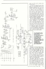
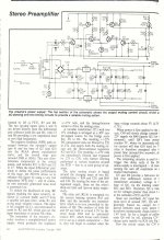
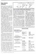
Here are the schematics and specs for their flagship no-frills preamp from 1990, designed by Rob Evans. There are a couple of other interesting things about this design of relevance to this discussion that prompted me to post them:
1) The strong emphasis on "Low Impedance Design" to achieve best noise performance - 22 years ago. Note the feedback Rs, right at the limits and probably lower than they should be so causing extra distortion?
2) Value of compensation caps and feedback caps around the 5534s - the feedback caps are quite large, presumably to define the upper rolloff. Is this perhaps a bad idea?
Would be interested to hear what all you very knowledgable chaps think...
Attachments
Thinking about this more, is putting large Rs in series with supplies to opamps (which I assume all have class B output stages) really a good idea?
Apart from the LP filtering, isn't it going to introduce a varying voltage drop, meaning the supply voltage is modulated by the current draw of the opamp's output stage? Assuming the load on the opamp output is heavy enough, just when there is a loud passage and the additional current draw is at its highest, the supply rails sag....surely not a good thing and potentially audible? Can any of the experts offer their thoughts on this?
Apart from the LP filtering, isn't it going to introduce a varying voltage drop, meaning the supply voltage is modulated by the current draw of the opamp's output stage? Assuming the load on the opamp output is heavy enough, just when there is a loud passage and the additional current draw is at its highest, the supply rails sag....surely not a good thing and potentially audible? Can any of the experts offer their thoughts on this?
Thinking about this more, is putting large Rs in series with supplies to opamps (which I assume all have class B output stages) really a good idea?
Apart from the LP filtering, isn't it going to introduce a varying voltage drop, meaning the supply voltage is modulated by the current draw of the opamp's output stage? Assuming the load on the opamp output is heavy enough, just when there is a loud passage and the additional current draw is at its highest, the supply rails sag....surely not a good thing and potentially audible? Can any of the experts offer their thoughts on this?
D'you know, I was having just that same thought either this morning or last night? Simple thoughts at first, because of course you want keep output impedance low and the supply stiff. And then more quantitive thoughts about how much they would move, and how quickly, and whether or not there would be a optimum between the two.
But, while a good way to easily model it hasn't yet popped into my head, it would seem to me to boil down to such and such a dV/dI, at whatever bandwidth. And that looks suspiciously like tailoring the output impedance. And from that point of view, short of putting the huge capacitor on the output alone, minimizing the effect of the inductance would imply a resistor. And since that would not do the whole job, a capacitor as well.
It could be well worth looking into, though the question still remains of whether you want the rejection to be getting poorer above120Hz (as it does) just so you could get a smooth output impedance. And, of course, the loads really aren't that low usually, though they are effectively just about in parallel for each op amp (ie, four or five of them will have their output voltages change by approximately the same amount.) Just some hand calculations could help here (though I haven't even done those). Oh, and you have to look at where the current into the 317 is coming from. Now, over to the experts.
To help explain look at Gootee's posts on decoupling and currents and transients.
I'll present a short version of Gootee's thoughts/experiments.
Attach an opamp to a regulated supply with a few short wires and PCB traces.
Attach a value for resistance and if you want extra complication capacitance and inductance. Now attach that tiny decoupling cap to the opamp power PINs.
The resistance/impedance prevent the power PINs seeing the regulated supply at VHF. The power PINs only see the decoupling. That is where the opamp gets it's current from to deliver to the load when a fast transient demands that current.
At the slower scale of bass notes, where small impedances have little effect then the power PINs do see way back along the supply lines. Then the current comes from a combination of all the decoupling and the regulator and if fitted any smoothing after the regulator.
These are all RC or LC filters as far as the power PINs are concerned.
One simply selects the different R&C to suit the opamp demands.
Thanks Andrew but I haven't been able to find those posts using the search function - could you post a link?
As I understand it at VHF the opamp shouldn't be doing anything unless it's oscillating. The small decoupling cap(s) are there primarily to prevent this by the mechanism you've just described, and Christian has stated their self-inductance is important which makes sense here. I fail to see how on their own they are very significant at audio frequencies though.
My pondering was on what happens when the opamp is amplifying audio frequencies and there is sufficient loading that the class B output stage draws significant currents in addition to its quiescent draw.
With a power amp, the (class B) output stage causes nasty half-wave rectified signals to be superimposed on the supplies, hence there is usually some RC filtering to the earlier stages to stop it getting in. But with an opamp you don't have this option, and it seems as though putting large Rs in series with the (common to all internal stages including class B output) supply could make things worse.
Would Mr Self and/or Mr Cordell be able to help steer us back on the straight and narrow here? 😱
you need to think impedance, frequency, compare regulator, bypass, PS trace RLC and op amp PSRR
DIY: solid state is good on regulators
below 1 kHz the common LM317 can have output Z well below 100 mOhm, somewhere in the upper audio depending on bypass C, possible damping Zobel the Z may peak to a few Ohms
so a heavy op amp current like 10 mA only gives <100 mV on the PS rail at the worst case frequency, this can be kept to 10 mV if you design the output bypass properly
op amp PSRR is at worst equal to the loop gain (for the rail the internal compensation cap is attached to)
a 20 MHz GBW op amp has 60 dB gain at 20 kHz
so for unity gain, today's faster op amps, a supply with ~1 Ohm max Z from proper
bypass/damping you only have 10 uV of PS loading PSRR/"noise"
a common assertion is that music has ~3 kHz power bandwidth - it is possible to trim the LM317 circuit for less than 100 mOhm Z below 3kHz
with those assumptions you only typically have ~ 1 uV PSRR error without "extreme" measures
Some nice points raised here. I agree with you jcx and AndrewT - the PSRR of modern op amps really can reduce some of these problems to insignificant levels if a few simple rules are followed.
That said, I do not believe 'stiff' power rails are needed and prefer to decouple each supply pin with a 22 Ohm resistor and a 100uF to a dedicated supply bypass ground rail. This results in only low frequency PSU currents flowing in the supply lines and here the op amp supply rejection is at its best (well above 100dB in many devices). Doing this, you also kill the wide band noise of the LM3xx devices, which after decoupling of the Vref pin can still be around 45uV on 15V rails.
It also helps to bias the op amp output stages into class A (nice bootstrapping trick from you btw jcx!) since this also results in very clean signals on the supply rails.
So, in summary, decouple locally, run op amps in class A, use a dedicated decoupling ground return and stick with LM3xx. No need for super regs, shunt's etc.
Last edited:
Thanks Andrew but I haven't been able to find those posts using the search function - could you post a link?
As I understand it at VHF the opamp shouldn't be doing anything unless it's oscillating. The small decoupling cap(s) are there primarily to prevent this by the mechanism you've just described, and Christian has stated their self-inductance is important which makes sense here. I fail to see how on their own they are very significant at audio frequencies though.
My pondering was on what happens when the opamp is amplifying audio frequencies and there is sufficient loading that the class B output stage draws significant currents in addition to its quiescent draw.
With a power amp, the (class B) output stage causes nasty half-wave rectified signals to be superimposed on the supplies, hence there is usually some RC filtering to the earlier stages to stop it getting in. But with an opamp you don't have this option, and it seems as though putting large Rs in series with the (common to all internal stages including class B output) supply could make things worse.
Would Mr Self and/or Mr Cordell be able to help steer us back on the straight and narrow here? 😱
Hi owdeo,
I just bypass every op amp's + and - rails to ground with a 0.1uF ceramic and usually sprinkle around some 10uF to 100uF electrolytics. The ESR of the electrolytics acts to damp any resonances formed by the low-ESR ceramics and rail inductances. The observation about half-wave-rectified currents from the class-B output stages of the op amp is astute. However, bear in mind that if these cause significant noise/distortion on the rails that is not obviated by PSRR, then measurable distortion will result. If you achieve very low measured distortion, this phenomenon is probably not at work. My experience is that this phenomenon does not result in measurable distortion. However, I must also say that I do not generally have op amps driving really low-impedance loads. I used this basic bypassing approach in my THD analyzer, where of course extremely low distortion was important and was achieved.
I do not subscribe to the idea of just having a single bypass capacitor from rail-to-rail on each op amp. This will tie the rails together at high frequencies, but may allow the rails to flop around with respect to the local ground. At high frequencies, I like to have it all nailed together locally.
Cheers,
Bob
- Home
- Source & Line
- Analog Line Level
- New Doug Self pre-amp design...