Wow, very very cool.. I think you are the first person I have seen in modern history to use tungar bulb rectifiers.. Certainly unique, can you share some schematics with us? I have no gut sense of how to implement rectification with tungar bulbs - can they handle significant capacitance (presumably they can since they were commonly used in antique battery chargers) and I assume you have lots of low dcr choke action going on.. Very lossy voltage wise or not?
😀
Hello from Athens, Greece.
Thanks for your comments.
I do not think that I'm alone. Most probably I'm alone here in DIYaudio but I do not think that nobody else has made such a craziness...
Schematics? Not necessary! It is so simple! Read the text above. You build the filament supply exactly like HV, nothing different! The problem is that you have to find the bulbs, they are almost totally unavailable. I collected several hundreds of them (around 350+ bulbs) years ago from a radio technician in New Delhi.
I am limiting 1st cap at 3.300 uF after performing some experiments. For mercury vapor rectifiers I prefer to stay at 1.000uF.
Surprisingly, they are not lossy voltage-wise. OK, more lossy than silicon but they still reach ~1:1 factor (e.g. 2x20VAC gives ~20VDC on first cap). Rather classic performance.
The most difficult part to build is the supply of tungar's filament. You need 2.25VAC and 35 amperes of current. Not an everyday task for the average coil winder.
Do not hesitate to ask if you would like further assistance.
Regards,
P.A.
My respect, from Warwick, UK. 35A of filament current! That certainly is extreme.... useful with Winter coming!
Do you measure improvements in rectifier-turn-OFF pulses with the Tungar rectifiers?
And softer turn-ON (slow rise in rectifier current, compared to silicon?)
Do you measure improvements in rectifier-turn-OFF pulses with the Tungar rectifiers?
And softer turn-ON (slow rise in rectifier current, compared to silicon?)
Tungar bulbs
Hi Rod.
Thank you for your good words.
35A of current is definately a big deal, but do not stick on this. It is nothing that extraordinary. I have wound 100s of transformers, have the experience, so for me it is not something that difficult or extreme. I have wound much more extreme transformers than this one... For example, one of the most extremes is the OPT of this amplifier, it is very complicated in structure, with exotic custom ordered magnetic cores and exotic ultra-expensive copper wire! It provides maximum load linearity under full power at 20Hz! This is one of the reasons of its amazing performance.
Measured ~17.5 amperes on each tube, filaments MUST be paralleled, so we get a total of ~35A of filament current. 4x 2.24mm copper wires in parallel.
I have not yet measured the improvements in diode turn-off pulses but it is certain that they follow the same rules like HV rectifiers. This is the reason that tube rectifiers ALWAYS sound better.
Now, something more useful for the people here in DIYaudio.com.
Today I have finished evaluating all alternatives for filaments heating (DHT of course). The listening impressions are rather straightforward, so I hope that visitors here could be benefited, or at least pushed to test further.
Guys, it is always impossible to hide the character of the electronic device used for filtration, either CCS or servo or whatever.
1. Let's start from the absolutely best solution: this is C-L(differential)-C-L(commom mode)-tube, no electronics at all. This works best for output stage at only 3-4 mV of ripple on lowdspeaker. For earlier stages you need another differential choke and a filtering cap, a total of 3 irons. Choke input sounds worse exacly as in HV applications. The drawback is that you need a very large c.m. choke with high inductance and very low DC resistance. If resistance is a bit high, wire gets heated and after a while the filament voltage drops below acceptable limits. This is the most crazy solution, most expensive and most difficult to elaborate.
2. In order to avoid this voltage drop, you can use e.g. an LT1083-4-5 in CCS mode right before the c.m. choke, not for AC filtration but for DC current stabilization only. Isolating the power supply is done through the cm choke, not the CCS! You have to bypass the CCS device with a very good sounding capacitor and this makes a rather shocking, unexpected sound improvement, quite close to the no-electronics-at-all solution described in #1. But you have no AC mains ripple rejection through CCS, so you still need to go with a differential choke. This way you can use more down-to-earth c.m. chokes. The extra power is consumed on CCS heatsink before the wire in C.M. choke gets heated, at thermal equilibrium power is mostly consumed on this cm choke's wire.
3. For the less perfectionists, you can use CCS solutions or complicated electronics circuitry. This is the more simplistic approach, no need to use cm chokes. It still sounds miles better that voltage regulators.
I mostly recommend #2 because the circuit is very stable and sonic performance miles better than CCS solutions with classic circuitry. And it is not that difficult to wind a CM choke. Start with 2.5 amperes per sq mm, and remember to bypass the CCS device with a top sounding electrolytic cap, as this bypassing gives super sound quality.
For driver tubes that ignite with low amperage like some old RE series from Telefunken (like my favorite RE074 Neutro) you can ommit CCS and at the same time have good stability on filament current.
Good luck!
P.A. from Athens.
My respect, from Warwick, UK. 35A of filament current! That certainly is extreme.... useful with Winter coming!
Do you measure improvements in rectifier-turn-OFF pulses with the Tungar rectifiers?
And softer turn-ON (slow rise in rectifier current, compared to silicon?)
Hi Rod.
Thank you for your good words.
35A of current is definately a big deal, but do not stick on this. It is nothing that extraordinary. I have wound 100s of transformers, have the experience, so for me it is not something that difficult or extreme. I have wound much more extreme transformers than this one... For example, one of the most extremes is the OPT of this amplifier, it is very complicated in structure, with exotic custom ordered magnetic cores and exotic ultra-expensive copper wire! It provides maximum load linearity under full power at 20Hz! This is one of the reasons of its amazing performance.
Measured ~17.5 amperes on each tube, filaments MUST be paralleled, so we get a total of ~35A of filament current. 4x 2.24mm copper wires in parallel.
I have not yet measured the improvements in diode turn-off pulses but it is certain that they follow the same rules like HV rectifiers. This is the reason that tube rectifiers ALWAYS sound better.
Now, something more useful for the people here in DIYaudio.com.
Today I have finished evaluating all alternatives for filaments heating (DHT of course). The listening impressions are rather straightforward, so I hope that visitors here could be benefited, or at least pushed to test further.
Guys, it is always impossible to hide the character of the electronic device used for filtration, either CCS or servo or whatever.
1. Let's start from the absolutely best solution: this is C-L(differential)-C-L(commom mode)-tube, no electronics at all. This works best for output stage at only 3-4 mV of ripple on lowdspeaker. For earlier stages you need another differential choke and a filtering cap, a total of 3 irons. Choke input sounds worse exacly as in HV applications. The drawback is that you need a very large c.m. choke with high inductance and very low DC resistance. If resistance is a bit high, wire gets heated and after a while the filament voltage drops below acceptable limits. This is the most crazy solution, most expensive and most difficult to elaborate.
2. In order to avoid this voltage drop, you can use e.g. an LT1083-4-5 in CCS mode right before the c.m. choke, not for AC filtration but for DC current stabilization only. Isolating the power supply is done through the cm choke, not the CCS! You have to bypass the CCS device with a very good sounding capacitor and this makes a rather shocking, unexpected sound improvement, quite close to the no-electronics-at-all solution described in #1. But you have no AC mains ripple rejection through CCS, so you still need to go with a differential choke. This way you can use more down-to-earth c.m. chokes. The extra power is consumed on CCS heatsink before the wire in C.M. choke gets heated, at thermal equilibrium power is mostly consumed on this cm choke's wire.
3. For the less perfectionists, you can use CCS solutions or complicated electronics circuitry. This is the more simplistic approach, no need to use cm chokes. It still sounds miles better that voltage regulators.
I mostly recommend #2 because the circuit is very stable and sonic performance miles better than CCS solutions with classic circuitry. And it is not that difficult to wind a CM choke. Start with 2.5 amperes per sq mm, and remember to bypass the CCS device with a top sounding electrolytic cap, as this bypassing gives super sound quality.
For driver tubes that ignite with low amperage like some old RE series from Telefunken (like my favorite RE074 Neutro) you can ommit CCS and at the same time have good stability on filament current.
Good luck!
P.A. from Athens.
Last edited:
Thanks Peter, great things to try out. BTW, what c-core size area and what type of winding (bifilar?) would you recommend for the cmc at about 1A DC. I should say for an inductance of 1 to 3H.
Common mode choke
Hello!
Try #2, you will be astonished! I promise it!
Now, regarding the CMC, inductance of 1 to 3 H is too low. Do not even think of trying it, absolutely worthless! If your cathode self bias resistor is say 1000 Ohms, then you have to reach at least 3 times this inductance at 30Hz through the CM choke! 2*pi*30*L=3*1000 -> Lmin=15.9 Henries!
I have tried several chokes and anything considerably lower than 3xRk takes back the great part of this amazing thing!
16H is not at the sphere of unobtainium, remember CM chokes do not have gaps and no DC bias, as they are wound on opposing chambers with reverse direction. In case you know the mu parameter of iron core material and the geometric characteristics, it is very simple to calculate the required turns. From available winding space you will calculate how many turns fit inside, so you select the core from the desirable winding window area.
Do not try bifilar winding scheme, just plain 2 chamber winding with opposing directions. Take a look at the pic, the CM choke is the big one between the wooden clamps, it is seen first with tungar bulbs behind it.
Thanks Peter, great things to try out. BTW, what c-core size area and what type of winding (bifilar?) would you recommend for the cmc at about 1A DC. I should say for an inductance of 1 to 3H.
Hello!
Try #2, you will be astonished! I promise it!
Now, regarding the CMC, inductance of 1 to 3 H is too low. Do not even think of trying it, absolutely worthless! If your cathode self bias resistor is say 1000 Ohms, then you have to reach at least 3 times this inductance at 30Hz through the CM choke! 2*pi*30*L=3*1000 -> Lmin=15.9 Henries!
I have tried several chokes and anything considerably lower than 3xRk takes back the great part of this amazing thing!
16H is not at the sphere of unobtainium, remember CM chokes do not have gaps and no DC bias, as they are wound on opposing chambers with reverse direction. In case you know the mu parameter of iron core material and the geometric characteristics, it is very simple to calculate the required turns. From available winding space you will calculate how many turns fit inside, so you select the core from the desirable winding window area.
Do not try bifilar winding scheme, just plain 2 chamber winding with opposing directions. Take a look at the pic, the CM choke is the big one between the wooden clamps, it is seen first with tungar bulbs behind it.
Last edited:
Hm, what do you mean #2? My Rk is 10 ohm because passing the filament current of 1A through it biases the 26 tube at -10V.
I intend to get the M4-11 core from alphacore, but they don't mention the mu parameter.
I intend to get the M4-11 core from alphacore, but they don't mention the mu parameter.
26 tube? Ok then!
For Autobiasing scheme, which is the value of Rk? This is very important. You must elevate the AC resistance (inductance) of the filament supply to more than 3 times Rk, so filament sound wave (sound that leaks out of filament) passes 'more easily' through Rk and not through filament supply and its parasitic capacitance. Remember Rk is theoretically the only place from which sound loop must be established, not through filament supply's parasitic capacitance. So the inductance of supply must be as big as possible!
Generally speaking, initial permeability of CRGO should be around 1000-1500 or so. This is where your calculation should be based. No gaps and no DC biasing. On small cores (cross sectional area 1 sq inch) it would be difficult to reach high L values. For 26 tube I would select the core with cross sectional area 32x32mm and winding window width 65mm. Wire diameter 0.75-0.80mm. This is enough for a two chamber CM choke with ~850-950 turns per chamber. Inductance will be really high. Start from this 'extreme' point in order to realise how good is a CM choke! Then you can scale down.
Good luck.
Peter.
Hm, what do you mean #2? My Rk is 10 ohm because passing the filament current of 1A through it biases the 26 tube at -10V.
I intend to get the M4-11 core from alphacore, but they don't mention the mu parameter.
For Autobiasing scheme, which is the value of Rk? This is very important. You must elevate the AC resistance (inductance) of the filament supply to more than 3 times Rk, so filament sound wave (sound that leaks out of filament) passes 'more easily' through Rk and not through filament supply and its parasitic capacitance. Remember Rk is theoretically the only place from which sound loop must be established, not through filament supply's parasitic capacitance. So the inductance of supply must be as big as possible!
Generally speaking, initial permeability of CRGO should be around 1000-1500 or so. This is where your calculation should be based. No gaps and no DC biasing. On small cores (cross sectional area 1 sq inch) it would be difficult to reach high L values. For 26 tube I would select the core with cross sectional area 32x32mm and winding window width 65mm. Wire diameter 0.75-0.80mm. This is enough for a two chamber CM choke with ~850-950 turns per chamber. Inductance will be really high. Start from this 'extreme' point in order to realise how good is a CM choke! Then you can scale down.
Good luck.
Peter.
Autobiasing?
If you do not use autobiasing scheme and have the negative supply for grid-cathode, things could be quite different. Have not yet tried it because I like the sound of autobiasing scheme.
If you do not use autobiasing scheme and have the negative supply for grid-cathode, things could be quite different. Have not yet tried it because I like the sound of autobiasing scheme.
Yes, autobias. Have a look at Andy's preamp; this is how I do it, except I'm using my own filament supply. The 1A current going through the filament and the 10 ohm resistor brings the cathode/filament 10 volts above the grid.
I'll go and do some reading on inductor winding and formulas. Thanks for your help!
I'll go and do some reading on inductor winding and formulas. Thanks for your help!
Attachments
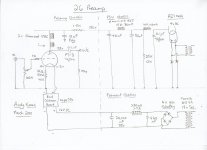
Yes, autobias. Have a look at Andy's preamp; this is how I do it, except I'm using my own filament supply. The 1A current going through the filament and the 10 ohm resistor brings the cathode/filament 10 volts above the grid.
I'll go and do some reading on inductor winding and formulas. Thanks for your help!
Yes,
this is autobiasing scheme.
10 Ohms cathode resistor. So go accordingly. You do not need excessively high inductance like in my case. But I use different schematic. Classic autobiasing scheme with filament voltage applied directly onto tubes pins, with both resistor and capacitor on the (+) side. Resistor for biasing and capacitor for zero feedback. CM choke imposes huge inductance so signal passes through capacitance more easily with less interference of parasitic capacitance of filament PS.
Finally, something for your PS. I see you use Telefunken mesh AZ1. FYI this tube loves bigger capacitance. 0.1uF is almost choke input. Try 10uF capacitance, it will play a lot better.
It is Andy's circuit. The only part that I use is the bias. My psu is different and I will change it again; I will wind myself some chokes for B+ filtering and plate load as well. Those should be simpler to make.
2. In order to avoid this voltage drop, you can use e.g. an LT1083-4-5 in CCS mode right before the c.m. choke, not for AC filtration but for DC current stabilization only. Isolating the power supply is done through the cm choke, not the CCS! You have to bypass the CCS device with a very good sounding capacitor and this makes a rather shocking, unexpected sound improvement, quite close to the no-electronics-at-all solution described in #1. But you have no AC mains ripple rejection through CCS, so you still need to go with a differential choke. This way you can use more down-to-earth c.m. chokes. The extra power is consumed on CCS heatsink before the wire in C.M. choke gets heated, at thermal equilibrium power is mostly consumed on this cm choke's wire.
It is not surprising that you had to bypass the LT1083. This device generates too much noise for DHT heating. This may sound surprising, but just consider that (for example) 0.1% of current noise in a 1.2A 300B filament is 1.2mA. The current noise is DIRECTLY mixed with the anode current of the DHT (maybe 60mA). You can do the calculation for % of anode current noise! Maybe it is better than 0.1% - but it will never be small enough. The capacitor will damp some of this noise, but will not remove it.
My Filament Heater kit does not contain any reference (bandgap, zener etc) because these generate too much noise. The effective reference is simply a base-emitter junction of a low-noise transistor {a few nV/(Hz^0.5) in other words}.
As for the difference in sound, Paul Needs, and Gianluca and others, have directly compared the LT108x:
http://www.diyaudio.com/forums/tubes-valves/38248-new-dht-heater-25.html#post2368003
The regulator also includes a passive Gyrator for mains AND high frequency filtering. Because it is passive (ie NO feedback loops at all) it performs sonically much the same as a choke. Of course, at low frequency it performs much BETTER than a choke. At VHF+ frequencies (which is very important for screening mains noise), one would need to build a choke with only few tens of pF across it, just to match the performance of the Gyrator.
We can put some honest numbers on the LT1083 noise, rather than just the hand-waving.
The data sheet specifies the noise as:
0.003% of Vout, Typical, 25 deg C, RMS value, 10Hz-10kHz.
When connected as a CCS, for say a 1,2A 300B filament, the regulator applies 1,2V across a 1-ohm resistor, so the output noise is:
Vn = 1,2V x 0.003% = 36uV;
and the noise current is translated by 1-ohm directly into amperes: 36uA.
So the CCS injects RMS noise of 36uA into your filament, where it is directly coupled to the cathode current.
For 300B at 60mA, this is RMS 0.06%
For 26 preamp at 6mA this is nearer to 0.5% (1.05A filament).
No wonder the difference is audible!
Remember, these are RMS values, so the peaks are bigger. For some samples of the chip, the noise will be worse, as it is not guaranteed.
And, if the test bandwidth were properly opened up to audio amplifier limits, the noise would be substantially worse.
It is not surprising that you had to bypass the LT1083. This device generates too much noise for DHT heating. This may sound surprising, but just consider that (for example) 0.1% of current noise in a 1.2A 300B filament is 1.2mA. The current noise is DIRECTLY mixed with the anode current of the DHT (maybe 60mA). You can do the calculation for % of anode current noise! Maybe it is better than 0.1% - but it will never be small enough. The capacitor will damp some of this noise, but will not remove it.
My Filament Heater kit does not contain any reference (bandgap, zener etc) because these generate too much noise. The effective reference is simply a base-emitter junction of a low-noise transistor {a few nV/(Hz^0.5) in other words}.
As for the difference in sound, Paul Needs, and Gianluca and others, have directly compared the LT108x:
http://www.diyaudio.com/forums/tubes-valves/38248-new-dht-heater-25.html#post2368003
The regulator also includes a passive Gyrator for mains AND high frequency filtering. Because it is passive (ie NO feedback loops at all) it performs sonically much the same as a choke. Of course, at low frequency it performs much BETTER than a choke. At VHF+ frequencies (which is very important for screening mains noise), one would need to build a choke with only few tens of pF across it, just to match the performance of the Gyrator.
Reality is exactly as you mention it!
LT devices produce noise. Cap bypassing was quite shocking to me, but you are right.
OK, the purity of the choke is probably unmatched but unfortunately you cannot go only with a choke as voltage drifts. Your solution at low frequency is definately better.
I would like to try it before this project ends. How would that be possible Rod?
Regards,
P.A.
LT1083
0,5% noise in driver tubes of ~4-6mA anode current is way too much indeed! And in my case this is differential so the CMC cannot block it! Maybe it would be better to 'hide' LT between the two differential chokes in a CLCLC filament solution but again filament chokes cannot supress noise that much.
How would it be possible to evaluate your solution?
So the CCS injects RMS noise of 36uA into your filament, where it is directly coupled to the cathode current.
For 300B at 60mA, this is RMS 0.06%
For 26 preamp at 6mA this is nearer to 0.5% (1.05A filament).
No wonder the difference is audible!
.
0,5% noise in driver tubes of ~4-6mA anode current is way too much indeed! And in my case this is differential so the CMC cannot block it! Maybe it would be better to 'hide' LT between the two differential chokes in a CLCLC filament solution but again filament chokes cannot supress noise that much.
How would it be possible to evaluate your solution?
Reality is exactly as you mention it!
LT devices produce noise. Cap bypassing was quite shocking to me, but you are right.
OK, the purity of the choke is probably unmatched but unfortunately you cannot go only with a choke as voltage drifts. Your solution at low frequency is definately better.
I would like to try it before this project ends. How would that be possible Rod?
Regards,
P.A.
Peter, you can click my name to send email/PM, if you like some information on the Regulator kits.
I have some PDF documents for the Regulator applications, with recommended transformer, rectifier etc (but you don't need that! even better with Tungar rectifier)!
Please include a return email address.
kit
I have observed that differences are quite more noticeable while using Tungar rectifiers. Maybe the absence of switching noise of the diodes leaves more clean room for such detection. So the slightest hint of noise is more perceivable.
I will drop you a PM right now.
Thanks,
Peter.
Peter, you can click my name to send email/PM, if you like some information on the Regulator kits.
I have some PDF documents for the Regulator applications, with recommended transformer, rectifier etc (but you don't need that! even better with Tungar rectifier)!
Please include a return email address.
I have observed that differences are quite more noticeable while using Tungar rectifiers. Maybe the absence of switching noise of the diodes leaves more clean room for such detection. So the slightest hint of noise is more perceivable.
I will drop you a PM right now.
Thanks,
Peter.
Hi Rod,
I know I have asked you before, but could you please PM me info on how I can order a set of these from you? Thank you. Again...
Hi, I sent some PM on Friday. If you haven't received it, please click my name to send some PM, or email. Plenty of information available about Filament Heating.
<snip...>
you can use CCS solutions or complicated electronics circuitry. This is the more simplistic approach, no need to use cm chokes. It still sounds miles better that voltage regulators.
I
Good luck!
P.A. from Athens.
Hi Peter, I am happy that you also find a big problem with Voltage Regulation applied to Filament Heating.
Nothing is worse than voltage regulators in this position.
With ac-heating you have high levels of 50/60 and 100/120 Hz cross-products, but at least this corruption is simple and constant.
With voltage regulators, a reference is necessary, and it is difficult to remove the noise from these. With IC voltage regulators, like the 317, it is impossible to remove the noise, and these make a bad solution in all cases.
But the biggest problem with voltage regulation arises because of the interaction between the filament supply and the cathode current.
The voltage across the filament (5V for 300B) means that there is an anode-cathode voltage gradient along the filament, and a grid-cathode gradient, also. This imbalance in the triode's operating voltage causes a music-signal to be developed across the filament terminals.
Now, this music-signal across the filament terminals is applied to the feedback network of the voltage regulator, since it is in the same place as the filament heating voltage. In other words, (part of) your audio signal is mixed up in the feedback of a voltage regulator that is ony supposed to be heating the filament. This is very bad, because the music signal is maybe only microamperes to mA, but the filament current is 1,2A for 300B. All voltage regulators have transient response errors, which do not usually matter if they are 0,1% of the output current. But think about 0,1% of 1,2A (1,2mA) applied to the mA music signal!
Also, think that the Voltage Regulator will think that the music signal is an ERROR, and will try to correct it!!! This is a very bad outcome for the audio signal.
It gets worse. IC regulators like LT108x (and all other ICs) also have an open-loop gain which decreases rapidly across the audio band. In the closed-loop, this means that the error-signal increases with frequency. The effect of this on the filament circuit is that the audio signal will suffer frequency-dependent cancelling by the voltage regulator!!
This is the reason that voltage regulated filaments sound muddy and confused. Don't do it!
- Home
- Amplifiers
- Tubes / Valves
- New DHT heater