Hi everybody,
in the last months i have developed a 50 watt class AB power amp with the employment of complementary Sony V-Fet 2SK82 2SJ28. The input and driver circuit was thought to employ also low voltage power supply. Another my will was to configure the output stage to have also voltage gain, so the result was a topology similar to trans-nova.
Input stage is a folded cascode, driver stage is configured as a simply bjt follower to add up the complementary signals for the power stage. The little caps in the circuit not are much necessary, but in audio test with my friends, seems better with it in.
In reality i have prepared 2 main driver circuit: one with all j fet cascode and another with jfet-bjt cascode.
Distortion measurement tell me that the best was version B (all jfet), but in audio test my friends prefer version A (jfet-bjt). This last has a faster and cheerful sound with more mid-bass and the sound seems more out of speakers.
Version B is preferred if it's necessary to put in evidence especially the high or if you prefer a more relaxed sound.
Francesco.
Attachments
How do they sound? Do you have any pictures showing the amps? I'm curious.
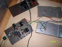
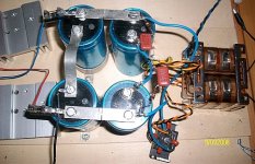
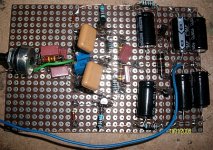
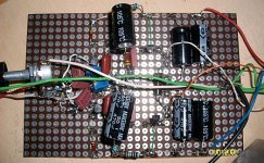
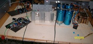
Hi, at this time i have realized only a prototype.
Here the photos. Sorry, Data of photo machine isn't current time.
Francesco.
Attachments
Hi people.
I have released a new other version of this amp.
You can see the figure also in my website:AMPLIMOS one stage amplifiers, amplificatori audio monostadio
There are others good schematics.😉
Francesco
I have released a new other version of this amp.
You can see the figure also in my website:AMPLIMOS one stage amplifiers, amplificatori audio monostadio
There are others good schematics.😉
Francesco
Attachments
It is currently only a prototype channel.
In the past, prompt I have made the PCB, but now I devote more time to optimize the schema and components employed, helping with listening sessions, before making the printed circuit boards.
If there is sufficient demand (GB?), I can achieve and provide the amplifers PCB (ver. A, B or C) with all components and also completed with power Vfets. 🙂
Francesco
Hi Francesco,
Last week I found 8 pcs of k79 and 4 pairs of K70 and J20 sitting nicely in a friend's electronic parts store. I am contemplating how to build an amp that brings out the sound characteristics of the parts. Very happy to have just discovered this thread.
However, I still could not understand how you get a voltage gain on the output stage vfet with source follower configuration as per your schema. Do you think that voltage gain on the output vfet is mandatory to realize the vfet sound characteristic?
Thanks in advance
Hi Francesco,
However, I still could not understand how you get a voltage gain on the output stage vfet with source follower configuration as per your schema. Thanks in advance
This output stage isn't follower configuration. See where the GND is applied: it is on the two emitters, so the output stage transistors are in common emitter configuration. Therefore on its Drains there is voltage gain. The amplified signal is then applied to output across the two big caps. This is "transnova" topology, and i have just choose this because it allow:
1) very simple driver circuit for Vfet or Sit final stage
2) voltage gain of the o/p stage
3) low voltage rails for input and driver stages. You can choose a better variety of active devices. Generally low voltage transistor have better performances than high V.
Do you think that voltage gain on the output vfet is mandatory to realize the vfet sound characteristic?
No at all. In the past Vfet are employed in source configuration (except in the Yamaha B1) so you can obtain a classical sound characters of ancient vfet amps.
But in my opinion the true sound of vfet are different.
This because when output stage is a follower, the swing amplitude of the signal is generated by first stages. So if for example we have a 3 stage amp with 1° and 2° stage realized with Bjt and the output stage with follower Vfets, the voltage gain is realized by first 2 stages. In that conditions the shape of the output signal is mainly due to the distorsion of these first stages. Vfet follower limits itself not to adds more distorsion.
But if you can choose from which devices you can obtain the need amplification, you sure choice the more linear component.
So i prefer Voltage gain realized from Vfet also, because they are more linear.
Vfet amplifier with voltage gain output stage moving on the reference compared to the old amplifiers known 😉
Francesco
Ok, I get it now, thanks for the explanation.
I'm planning an amp with the K79 vfet input followed with a 2SA929 and bootstrapped 2SC1845 bjt follower to drive the transnova output stage.
Due to my rusty skill and a very busy schedule, development will be very slow. However, I will post progress and schematic along the way.
I value any suggestion that you may have.
Mos, thanks for the circuit. I would like to try some SIT as well. Is ur circuit input single ended and the bulk of the front end is doing inverting?
If I already have a balance output from my preamp, how would I change the circuit?
If I already have a balance output from my preamp, how would I change the circuit?
Mos, thanks for the circuit. I would like to try some SIT as well. Is ur circuit input single ended and the bulk of the front end is doing inverting?
If I already have a balance output from my preamp, how would I change the circuit?
Hi, complementary circuit not need of phase inverter.
If you have a balanced preamp, you need of differential amplifier on the input stage as in the following schematic
Attachments
Hi Francesco,
In all your versions of this interesting circuit you use a CT transformer, however I see that you only connect the center tap to a sort of snubber (if I got it correctly), and not to the loudspeaker. Can you please clarify if we could for example use only one 60V transformer bobbin instead of 2x30V?
Also what value would you set the output idle current at in this power amp?
Thanks for your time and for sharing the design!
Hi Francesco,
In all your versions of this interesting circuit you use a CT transformer, however I see that you only connect the center tap to a sort of snubber (if I got it correctly), and not to the loudspeaker. Can you please clarify if we could for example use only one 60V transformer bobbin instead of 2x30V?
Also what value would you set the output idle current at in this power amp?
Thanks for your time and for sharing the design!
Yes, of course you can use a transformer with a single secondary.
For best results it is important to use splitted spools for primary and secondary windings or with electrostatic screen between them. Double C core firstly or E-I types are preferred. I not advice toroidals.
The bias was set at around 150 mA.
Vfets and output capacitors must be matched!
Last edited:
Yes, of course you can use a transformer with a single secondary.
For best results it is important to use splitted spools for primary and secondary windings or with electrostatic screen between them. Double C core firstly or E-I types are preferred. I not advice toroidals.
The bias was set at around 150 mA.
Thanks! I found some 120VA R-cores at Selectronic, but I guess the value is too low...
Vfets and output capacitors must be matched!
That would be tricky, as I have VFETS with different letters (E and F). But of course, i understand why you need to match these... probably this will be a show stopper unfortunately 🙁
Grazie!
Hi Francesco,
I would have one more question, sorry if I am off-topic. In your circlotrone schematic for 2SK180 you use for the input stage a dual supply, right? (+, 0 and -42V).
I expect that one can easily adapt the input to take differential voltage. (make the lower transistor stage as the upper one and the 100k input shared between them). Can you please comment on these?
Thank you in advance!!
Hi Francesco,
I would have one more question, sorry if I am off-topic. In your circlotrone schematic for 2SK180 you use for the input stage a dual supply, right? (+, 0 and -42V).
I expect that one can easily adapt the input to take differential voltage. (make the lower transistor stage as the upper one and the 100k input shared between them). Can you please comment on these?
Thank you in advance!!
Yes you are right, just you do a mirrored input circuit as the top half.
These types of circuits are natively designed to accept balanced signals and the obtained overall performance can be improved only.
More than 10 years ago I made a circlotron with latfet which was used to connect balanced or unbalanced signals. 😉
http://www.amplimos.it/images/CIRCLOTRON_50W.bmp
Yes, thank you, that answers completely my question 🙂 Coming back to the VFET Circlotrone, is it designed so as VFETS are running a class AB? If yes, the current is still 150mA or is it different?
Nice evening and thanks again!
Nice evening and thanks again!
Hello mos57. US patent 4,467,285 was granted to inventor James C. Strickland who gave us the TNT-200 amplifier. Great read.
Are you showing a Class AB amp without global NFB?
Are you showing a Class AB amp without global NFB?
Yes, thank you, that answers completely my question 🙂 Coming back to the VFET Circlotrone, is it designed so as VFETS are running a class AB? If yes, the current is still 150mA or is it different?
Nice evening and thanks again!
Hi, I have desesigned it for class AB, so 150 mA is a good start of point, but with minimum shifting in Vgs bias you can easily go in pure class A up to 50 or more watt, being 300 watt in dissipation for each device.
Of course you need a greater transformer and psu capacitors and cokes.
Remeber also that preamp section must be On before the output stage
Best regards.
- Status
- Not open for further replies.
- Home
- Amplifiers
- Solid State
- New complementary V-FET amp: Best from the past ?
