sorry for my offtopic. DjLeco eu am gasit cu 12 ron bucata de irfb4227 la adelectrocom. dar nu imi vine sa cred ca ai dat 6 milioane  Daca stii undeva mai ieftin zi-mi si mie.
Daca stii undeva mai ieftin zi-mi si mie.Pai
Pai eu am comandat de la farnell...
Numai de acolo comand,stiu 100% ca sint piese originale.
Ia citeva de unde zici tu, si pune niste poze sa le vedem
Pai eu am comandat de la farnell...
Numai de acolo comand,stiu 100% ca sint piese originale.
Ia citeva de unde zici tu, si pune niste poze sa le vedem
Are
Are one of those toroids good for class D output coil?
http://www.ferroxcube.com/prod/assets/tn332011.pdf
Wich one is better?
Are one of those toroids good for class D output coil?
http://www.ferroxcube.com/prod/assets/tn332011.pdf
Wich one is better?
The one with the lower permeability is the better, but we don't know weather it's usable or not, since there is no any of the quality specs. There is a little hope, at least for small power.
Pafi said:The one with the lower permeability is the better, but we don't know weather it's usable or not, since there is no any of the quality specs. There is a little hope, at least for small power.
Oki.
That means the one with red is the best, no?
An externally hosted image should be here but it was not working when we last tested it.
I answered to your mail, twice with 2 new offers!.
Waiting for last details, for exchange.
Trying to use it at 250 Khz, the IR2110 getting a little hotter than at 125 Khz.
Added ZTX 851+951 Buffers between IR outputs and mosfets and everything is OK and cold.
The output coils has been downgraded at 20uH each for 250 Khz and 33uH for 125 Khz carier.
Seems those values been optimally for those freq.
The output tension raised to 64V RMS till clipping prag, when power supply dropped to 87 volts in max load , from 95VDC in idle, on 4 ohms speaker.
I have added also in parallel on speaker, a dummy load of 4 ohms/500Watts resistor, to see what's happening.
The output voltage dropped to 54 V RMS till clipping, when powersupply,dropped to around 77VDC, all in 2 ohms!
The output heatsink is around 40 degrees fanless.
Maybe later some new pictures and a little movie.
Back
I was walked away,now back to this job.
Any ideea at wich amperes will saturate those TDK RM14 cores with 1mm airgap(oficial unmodified), for 20-25uH inductance (decreased from oficial 80uH)?
Lovering the inductance, will increase saturation current?
Also HOW I seen on scope when core saturates?
Where I must connect probes of scope to see that?
How I can seen on scope too, the deadtime between LM361 outs and output mosfets (oficial deadtime)?
I have a analog 2 channels Goldstar oscilloscope 2x20Mhz.
Any ideea for BD architecture fullbridge ground referenced?
Doesn't found any schematics on google...
I will give a try to transform it into BCA amp because, till now, experiencing, I burned some IRFB4227, in full bridge mode drived by IR2110+ZTX buffers and I presume modifying into BCA, doesn't exist risk of shoot-through destroying output devices.
Also, a question, studying BCA configuration, I observe it both mosfets are in conduction On-Off as same time, also BCA style output, can be done with final stage drived in contratimp (IR2110)?
Waiting...
Hey
If core saturates, its inductance will fall a lot, I think it was said, it becames air inductor, current will increase a lot, probably destroying your fets
If core saturates, its inductance will fall a lot, I think it was said, it becames air inductor, current will increase a lot, probably destroying your fets
luka said:Hey
If core saturates, its inductance will fall a lot, I think it was said, it becames air inductor, current will increase a lot, probably destroying your fets
Ok, presuming the core it saturates,how can I seen that on scope?
Where I must put scope probes to observe core saturation?
Putting 2 cores in parralel, it will double current saturation (2xRM14 of 20uH in parralel for each bobine, total 4 RM14 per amp)?
Also presuming my geccaloy cores are ok for my intention (just presuming) putting 2 cores sandwich like in photo, I will increase current capability?

Momentan I wait for Pafi's cores to arrive.
yes using 2 cores will allow you to use more current. You have to look at current that goes into core, when it starts to go up very fast, you are in saturation

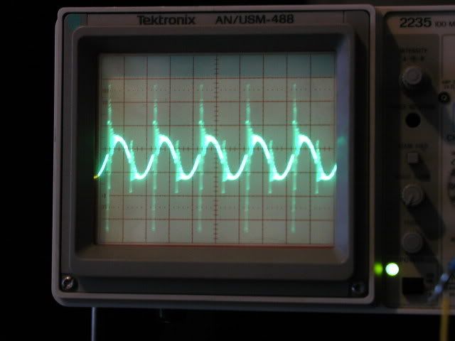
you see how it is linear, then it snaps? there is saturation starting/is
you see how it is linear, then it snaps? there is saturation starting/is
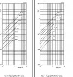
Ouroboros said:The attached data from Ferroxcube shows the range of I-squared x L for different RM cores and different gaps. Epcos cores will have virtually identical characteristics.
Thank you but I don't understand nothing from there...
What is I2L from that tabel?
How can it be converted in Amperes?
Don't laugh on me, but Im at beginning in that kind of stuff.
luka said:yes using 2 cores will allow you to use more current. You have to look at current that goes into core, when it starts to go up very fast, you are in saturation
you see how it is linear, then it snaps? there is saturation starting/is
Luka, where have you measured that?
I mean, where I must put oscilloscope probe, to measure?
In parallel with core?
In paralel with a shunt series resistor?
Also I found that about my Dark Blue cores Genalex:
Those are their producers:
http://www.sailcrestmagnetics.com/
And reading on their site , mine cores are Dark Blue Coated G1 series (R50 core), looks to be MPP cores, like here:
http://www.sailcrestmagnetics.com/products_powder_mpp.htm
Scroll down and you will see G1 part number in that tabel.
Also I doesn't found mine G1W 88 S540 core properties, I will try to E-mail them.
I have winded 10 turns of 200x0.08 lits and the inductance is around 10-11uH, how that pictule looks (in short, the Lmeter looks around 0.002):
An externally hosted image should be here but it was not working when we last tested it.
Reading on their website an anyone tell, if those cores are suitable for classD, or wich from there are suitable?
I didn't measure this, but you have to measure *current* that goes into the core. I hope you know how to measure current with scope, you have to know some resistance in series with core, and what voltage will it give at some current... and you do this outside amp, this will stay the same no matter what is the application
And you inductance measuring is probably off somewhat, measuring uH on 2mH scale is bad
And you inductance measuring is probably off somewhat, measuring uH on 2mH scale is bad
Here are some approximate formulae for the calculation of air gaps:
http://www.diyaudio.com/forums/attachment.php?s=&postid=196536&stamp=1056440860
Regards
Charles
http://www.diyaudio.com/forums/attachment.php?s=&postid=196536&stamp=1056440860
Regards
Charles
I-squared x L curves are very useful to check if a core is adequate for your required inductance and peak current.
Imagine you want a 20uH choke to carry a peak current of 10A without saturation. I^2 x L will be 10 x 10 x 20E-6 = 0.002 Joules (2mJ).
From the nomograph, you can see that an RM8 with a 1mm gap will be ok.
Imagine you want a 20uH choke to carry a peak current of 10A without saturation. I^2 x L will be 10 x 10 x 20E-6 = 0.002 Joules (2mJ).
From the nomograph, you can see that an RM8 with a 1mm gap will be ok.
luka said:I didn't measure this, but you have to measure *current* that goes into the core. I hope you know how to measure current with scope, you have to know some resistance in series with core, and what voltage will it give at some current... and you do this outside amp, this will stay the same no matter what is the application
And you inductance measuring is probably off somewhat, measuring uH on 2mH scale is bad
Really I'm not so sure about how to measure current with oscilloscope, but I think is usual to series output coil with ex 0,5 ohms and read the tension on it, no?
But how I know when exactly core saturates, because increasing output amplifier, it increase the output curret proportionally with output power...
I will "read" a rapid current increasing?
Or?
And if is in fullbridge mode, I must measure current on both coils, no?
Also, Luka, did you look at sailcrest website, the on that produces the blue cores that I have?
What can you tell?
Wich is the best from there for output coils on classd?
Regarding the value that my L-meter shows, is correct, I have tested them with output coils from an Crown XTI 4000 coils (10uH +/-5%) and it showed me 12uH, that is ok and accurate,vecause in short, my L-meter shows around 2uH.
Also testing a 500uH from Crown CE4000 PFC cores, it shows 511uH one and 507uH the second.
So If I have good understand,it could be used 2 or 3 cores for growing up saturation current, that's GOOD!😀
Also, presuming the RM14 core (the ones that I have) will saturate at 12-15A at 80uH inductance, reducing their inductance to aprox 30uH, the saturration curect will be double aprox?
I mean, if inductance is smalled by half, the current will aprox double?
My actual amp configuration is like in picture attached:
I drawed just base schematics,not decoupling condensers, and other stuff.
I used 470 pf with 10 ohms series snubbers and only a pair of IRFB4227
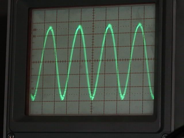
Running my amp now at 97 Vdc in idle dropping to 87 Vdc in full load, it works ok on speaker load (4 ohms), giving around 63-64 Vrms till clipping prag, output sinusoid clipping equally on tops of it.
Undistorted audio between 20 Hz to 300 Hz, everithing is OK.
If i put in parralel on speaker another 4 ohms resistive load, even at low levels on outpus, is a little distortion like a underbiased class AB amp, but the output on scope looks ok.
Pushing till clipping prag, the sound is the same,output sin is still correct, undistorted, clipping arises around 54 Vrms on out, and power supply dropping to around 75 Vdc.
Randomly,sometimes it pop up the 15A fuse seried with amp , and always found 2x IRFB4427 in short, only on High part of amplifier...
If I let only on speaker it works perfectly hours, no any trouble, just fearing to not destroy the speaker voicecoil.
Now the Question is:
It blows up mosfets because isn't enough one pair to drive 2 ohms, or something else is happening?
Looking at specs of IRFB4427, continuous Drain current is 46A@100 celsius degrees,and 65 A@25 celsius degrees, and my heatsink fanless temperature is around 40 celsius degrees after 30 minutes on speaker around 80% till clipping, and around 55 celsius degrees with 4 ohms dummy load in parralel on speaker(typically 2 ohms loading)..
What is bad here?
Maybe the feedback?
Could be shoot-througs?
Could the output coils saturating?
Can I modify that schematic to make it BCA output?
On BCA output tipe is absolutely necessary both mosfets turn on and off at same time(like Crown K series), or could be used in another way of modulation (push pull) like here?
An externally hosted image should be here but it was not working when we last tested it.
Here is my block drawing, excluding decoupling capacitors, and other supplyes and stuff etc, etc:
Excuse ugly drawing and full size...
An externally hosted image should be here but it was not working when we last tested it.
Ouroboros said:I-squared x L curves are very useful to check if a core is adequate for your required inductance and peak current.
Imagine you want a 20uH choke to carry a peak current of 10A without saturation. I^2 x L will be 10 x 10 x 20E-6 = 0.002 Joules (2mJ).
From the nomograph, you can see that an RM8 with a 1mm gap will be ok.
OUROBOROS, thank you for explanation.
So a 20uH on RM14, will saturate at how many amperes(1mm airgap)?
Hey
I did kinda say you will do that outside the amp
and 0.5R is bit, something like 0.01 is much better, NONE inductive resistor
You will need to put pulses on inductor, with some freq, and you will have to be able to adjust pulse width, or you won't be able to see anything...
Here comes part, that I would say, again, it is not easy to build d amps, not if you want to know where and how things will work, in other case, you can size your components, like inductor and use far too big one, at least you'll know it won't saturate
No I didn't look at that site
If your HI side fets go, this could mean your bootstrap C is not big enough, and I assume this happens during clipping, right?
compared to this
I did kinda say you will do that outside the amp
and 0.5R is bit, something like 0.01 is much better, NONE inductive resistor
You will need to put pulses on inductor, with some freq, and you will have to be able to adjust pulse width, or you won't be able to see anything...
Here comes part, that I would say, again, it is not easy to build d amps, not if you want to know where and how things will work, in other case, you can size your components, like inductor and use far too big one, at least you'll know it won't saturate
No I didn't look at that site
If your HI side fets go, this could mean your bootstrap C is not big enough, and I assume this happens during clipping, right?
You can check thisCould be shoot-througs?
compared to this
luka said:Hey
I did kinda say you will do that outside the amp
and 0.5R is bit, something like 0.01 is much better, NONE inductive resistor
You will need to put pulses on inductor, with some freq, and you will have to be able to adjust pulse width, or you won't be able to see anything...
Here comes part, that I would say, again, it is not easy to build d amps, not if you want to know where and how things will work, in other case, you can size your components, like inductor and use far too big one, at least you'll know it won't saturate
No I didn't look at that site
If your HI side fets go, this could mean your bootstrap C is not big enough, and I assume this happens during clipping, right?
You can check this
compared to this
My bootstraps capacitor is 10uF/25Vdc, sunted with 100nF ceramic(50Vdc).
Both mosfets on positive side of part of the amplifier(the one with positive feedback) fails(shorted) , the ones from the negative part(negative feedback) survives.
No troubles at full clipping, is clipping like an AB amplifier and what is curious, both alternances clipping the same,without ringins on output.
Tomorrow I will replace the died mosfets, and I will make some small movies, to see.
Any schematic for making banktest for output coils saturation?
Those resistors (0.04 ohms) are OK?
I have 10 pieces of it...
http://ro.farnell.com/welwyn/oar3-r040fi/resistor-1-0r040/dp/1200371
Hey
and my was 100u backed up by 100u 😉
About schematic... hmm.. not sure if I got any
It could look something like this
And you should see, again, somethig like this, see how is linearly goes up, with rating dI/dt(I hope I wrote this right)...seach google

and my was 100u backed up by 100u 😉
About schematic... hmm.. not sure if I got any
It could look something like this
An externally hosted image should be here but it was not working when we last tested it.
And you should see, again, somethig like this, see how is linearly goes up, with rating dI/dt(I hope I wrote this right)...seach google
- Status
- Not open for further replies.
- Home
- Amplifiers
- Class D
- New ClassD project Starting from 0