You say 2mm air gap is enough, or need more?
Is there a problem that the polished surfaces are NOT perfectly planes like the original gap?
Not perfect planarity is not a big problem. Actually with a rounded edge the I-H curve can be a little more linear.
2 mm with 20 turns results saturation current of 25...30 A, so it's still not enough. Number of turns can be decreased somewhat, but if you exaggerate it, idle current will start to grow. Basically these cores a little small for this monster amp, as I already wrote. You can use 4 sets of RM14 per amplifier, or change modulation mode and filter topology, increase freq, etc...
Telling I want to use those output coils for 2 ohms and 4 ohms speakers,presuming I gave around 100V RMS at output, suplying the power module with 140Vcc 20Amps.
You still haven't tell how much is "lower" and "higher" current!
Use Micrometals RF iron powder materials (like -2, -6, etc...). You will never achieve what you want with these cores and litz wire, unless you use several in series/parallel for each output leg.
I'm working on a project similar to yours but it's almost completed (including the usual pro-audio features like a limiter activated by clipping and most faults to avoid shutdown). My current limit is 72A. Supply voltage is 170V.
I'm working on a project similar to yours but it's almost completed (including the usual pro-audio features like a limiter activated by clipping and most faults to avoid shutdown). My current limit is 72A. Supply voltage is 170V.
Eva said:Use Micrometals RF iron powder materials (like -2, -6, etc...). You will never achieve what you want with these cores and litz wire, unless you use several in series/parallel for each output leg.
I'm working on a project similar to yours but it's almost completed (including the usual pro-audio features like a limiter activated by clipping and most faults to avoid shutdown). My current limit is 72A. Supply voltage is 170V.
Can you post some pictures of your output coils?
No
No way to run with IRFP260N,😡 , everything is OK till clipping level, when it heard a poc (like a hammer on the wall) on speaker and on scope, negative part of sinwave seems to dissapear..
If I push a little MORE than beggining of clip level, where this anomalous behaviour arise, it work in in clipping mode without that poc, but lowering again, it happens again.
I replaced IRFP 260N, again with IRF540, and works perfectly .
I tryed to replace the ferrite piece, with the ones that I have increased the air gap, and reaching it's max power, before entering into clip, the mosfets(irf540) failed...
Replaced again all 4 mosfets, put again original ferrite pieces of RM14, is working ok...
Growing up power supply above 105 Vcc in idle, all 4 IRF 540 have exploded, looks I have reached their 100Vcc D-S tension:
  ...
...
A question, could I use some TC44xx after output of IR2110 , like a buffer, to increase output current, to drive large mosfets?
Or what can I do, the IR540 wich works perfectly, are to small for what I want...
Any suggestions?
Any other model of N MosFets,wich could be drived well by IR2110?
No way to run with IRFP260N,😡 , everything is OK till clipping level, when it heard a poc (like a hammer on the wall) on speaker and on scope, negative part of sinwave seems to dissapear..
If I push a little MORE than beggining of clip level, where this anomalous behaviour arise, it work in in clipping mode without that poc, but lowering again, it happens again.
I replaced IRFP 260N, again with IRF540, and works perfectly .
I tryed to replace the ferrite piece, with the ones that I have increased the air gap, and reaching it's max power, before entering into clip, the mosfets(irf540) failed...
Replaced again all 4 mosfets, put again original ferrite pieces of RM14, is working ok...
Growing up power supply above 105 Vcc in idle, all 4 IRF 540 have exploded,
looks I have reached their 100Vcc D-S tension: ...A question, could I use some TC44xx after output of IR2110 , like a buffer, to increase output current, to drive large mosfets?
Or what can I do, the IR540 wich works perfectly, are to small for what I want...
Any suggestions?
Any other model of N MosFets,wich could be drived well by IR2110?
When you start to push the amplifier, all the design details that you are overlooking or ignoring start to matter a lot.
Start by measuring saturation current of output coils and adjusting gap and turns until you get the required level.
Then use oscilloscope to investigate waveforms until you find what is disturbing the amplifier, it will usually happen above a certain current level and be related to layout parasitics and body diode reverse recovery.
Be prepared for SMD and two layer (or more) PCB with ground/power planes because you won't be able to properly handle that much current in any other way.
Forget about veroboard and point to point, I did my first SMPS prototypes that way 10 years ago too...
Eva
Eva, the point is, I tested at 94Vdc with IRFP260N, doesn't want to work...
At same tension, in same conditions, and "In Air montage"it works pefectly with IRF540...
Also anyone is selling micrometals cores?
Where I can buy it?
And wich are their full code,if I want to try to order???
I'm waiting for advices about output devices mosfets, wich can be drived by IR2110, irfp260 are very unusable with IR2110
Is there a better driver than IR2110 , more powerfull?
Is OK to use a MBR20200CT,200V Schottky diode between D-S pins of mosfet , it helps?
http://www.datasheetcatalog.org/datasheet2/1/031x8odq7pjat132od2lpae46jfy.pdf
Also I see no-one is helping me recomanding output mosfets type, and antiparallel diodes, wich can be used...
Is so secret????????????🙁 🙁 🙁
- Read this topic through again!
- Use double-side PCB, with ground plane!
- Use your oscilloscope!
- Try to understand what happens in your circuit!
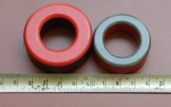
I can trade 8 pcs of micrometal T184-14 (OD=47, ID=24, H=18, Al=28) for 200*0.08 litz wire if you want (6 m litze = 1 core).
- Use double-side PCB, with ground plane!
- Use your oscilloscope!
- Try to understand what happens in your circuit!
I can trade 8 pcs of micrometal T184-14 (OD=47, ID=24, H=18, Al=28) for 200*0.08 litz wire if you want (6 m litze = 1 core).
Also I see no-one is helping me recomanding output mosfets type
How many times should we write that we recommend IRFP4227? (Or IRFB4227!)
Deal done!Pafi said:I can trade 8 pcs of micrometal T184-14 (OD=47, ID=24, H=18, Al=28) for 200*0.08 litz wire if you want (6 m litze = 1 core).
Put please some pictures of it with a centimeter near it,I want to see them!
Also, you didnt't told me enything about antiparallel diodes..
Speak tomorrow, also I will order 4227.
Single antiparallel diodes don't work, but you don't have to avoid body diode conduction completely either.
For example, my amplifier does not use any diodes, except for IR2110 protection against transients. Bu it works properly and allows to switch that much current (with some body diode conduction) because layout is good, all resonances were tamed, and timing of gate drive is very precise. That was achieved by looking at waveforms and changing whatever was required until they looked good. Two IR2110 are driving four pairs of IRFB4227 (buffer transistors required for high switching freqs).
As you learn to properly capture and interpret waveforms, you find answers to all your questions.
Also, waveforms may usually tell you when something is going to explode at a higher current or voltage and why.
You may think that it's working well with IRF540, but if you look at the waveforms in detail, you will probably find lots of ringing and voltage spikes already exceeding IRF540 and IR2110 ratings.
Eva said:...
You may think that it's working well with IRF540, but if you look at the waveforms in detail, you will probably find lots of ringing and voltage spikes already exceeding IRF540 and IR2110 ratings.
Good point Eva!
As usual, you don't get what you expect - you get what you inspect.
=========================
Pafi
Thanks for the explanations provided herein.
Even a caveman can understand them.

With IRF540, I looked, there's no ringing, not at IR2110 outputs, also not at outputs of amp...
When I'm come back from Italy (21 this month), will speak again, monday , I'm leaving...
Till then, I will order some IRFP4227.
When I'm come back from Italy (21 this month), will speak again, monday , I'm leaving...
Till then, I will order some IRFP4227.
You have to look at Vgs of the lower FET synchronizing the oscilloscope with comparator output, so that amplifier propagation delay helps to compensate oscilloscope trigger delay. You have to look at 50ns/div to really see turn-on and turn-off behaviour. This waveform has a very particular shape when everything is right. See pictures...
When there is some dead time but everything is otherwise right, switching with some signal and load looks like this (IRF540Z):
Removing dead time, it looks like this:
These gate turn on waveforms are more square than usual and the turn off waveform has some negative overshoot because this amplifier uses ferrite beads of specific size rather than gate resistors. I went back to resistors in newer projects because beads have high tolerances and are very hard to match.
You also have to look at comparator output and/or comparator inputs and ensure that there is no disturbance causing multiple pulsing when output voltage approaches the rails or when body diode recovery begins to produce high current peaks (and high EMI) , which is also an usual cause of hard to explain failures.
When there is some dead time but everything is otherwise right, switching with some signal and load looks like this (IRF540Z):
An externally hosted image should be here but it was not working when we last tested it.
An externally hosted image should be here but it was not working when we last tested it.
Removing dead time, it looks like this:
An externally hosted image should be here but it was not working when we last tested it.
An externally hosted image should be here but it was not working when we last tested it.
These gate turn on waveforms are more square than usual and the turn off waveform has some negative overshoot because this amplifier uses ferrite beads of specific size rather than gate resistors. I went back to resistors in newer projects because beads have high tolerances and are very hard to match.
You also have to look at comparator output and/or comparator inputs and ensure that there is no disturbance causing multiple pulsing when output voltage approaches the rails or when body diode recovery begins to produce high current peaks (and high EMI) , which is also an usual cause of hard to explain failures.
Yes
Yes,Pafy, nice cores!
So , how many pieces from the bigger one, do you have it (the full red one) ?
Yes,Pafy, nice cores!
So , how many pieces from the bigger one, do you have it (the full red one) ?
Pafi said:I think it's better to arrange the details in private!
You have an e-mail, also I left you my yahoo messenger ID, I'm waiting for yours.
Hello!
I'm afraid I won't get that e-mail. I got something in the past some hours, but it had been deleted as spam. Where did you send it, with what subject, and what is your e-mail address? I don't yahoo. You can reach me on pete dot eagle at gmail dot com .
I'm afraid I won't get that e-mail. I got something in the past some hours, but it had been deleted as spam. Where did you send it, with what subject, and what is your e-mail address? I don't yahoo. You can reach me on pete dot eagle at gmail dot com .
- Status
- Not open for further replies.
- Home
- Amplifiers
- Class D
- New ClassD project Starting from 0