hello,
would there be an intellectual property infringement if a company sells three small PCBs, or carrierboards, about 1.5 by 1.0 inch tall, fitted with SMDs, ready to use, providing each one a specific Class AB biaising scheme :
- "New Class A" bias module (see Technics folklore - synchro bias)
- "Super-A" bias module (see JVC folklore)
- "Non Switching" bias module (see Pioneer folklore)
The idea is to help hobbyists designing their own audio power amplifiers, making an effortless revival of the three non-switching class AB biaising methods. Hobbyists and designers would integrate the module of their choice onto their own main board.
Technics "New Class A" is relying on fast diodes, implementing a dynamic switch that is automatically chosing between the voltage that's coming from the driver (this is when the output device is pushed to drive the load), and between a fixed voltage that is preset and defining the minimum bias current (this is when the output device gets pulled out, with the load being driven by the other half).
Looks fine, apart from the inherent switching nature of the process. Technics engineers used to call it "synchro-bias", but the marketing rejected that name, and coined "New Class A" for very understandable reasons. I guess that nowadays ultrafast diodes can be used, specified with a less than 10ns switching time, an order of magnitude faster than the output devices.
JVC "Super-A" monitors the sum of Vbe of all output devices, plus the voltage drop that occurs on the 0.22 Ohm emitter resistance. This voltage gets then compared to a fixed threshold (like 2 Vbe in case of a Darlington), and when the total voltage gets beyond this threshold, plus a little something, a transistor fitted into the Vbe multiplier arrangement acts to gently increase the multiplication coefficient.
Looks weird, like a positive feedback ! The increase rate must remain well controlled.
Pioneer "Non Switching" monitors the sum of Vbe of all output devices, plus the voltage drop that occurs on the 0.22 Ohm emitter resistance. This voltage gets then compared to a fixed threshold (like 2 Vbe in case of a Darlington), and when the total voltage gets beyond this threshold, plus a little something, a transistor fitted into the Vbe multiplier arrangement acts to gently increase the multiplication coefficient.
In essence, this is exactly as JVC "Super-A". Pioneer scheme needs a supplementary current source, which would make transistor count higher than JVC "Super-A", but on the other hand Pioneer takes some shorcuts regarding the Vbe multipliers, saving transistors over there.
What about the LT1166 ? It is an integrated circuit from Linear Technology specially designed for biaising Class AB amplifiers. Would be a 4th module welcome, embedding a LT1166 ?
Don't you think that with the advent of Class D audio amplifier, there will be some hobbyists wanting to confront Class D sound with some other (older) technologies, that one cannot find anymore, like those three fancy Class AB biasing schemes dating back from the early eighties, and possibly the LT1166 way also, which is more recent ?
thanks for taking the time for reading
Attachments
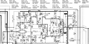
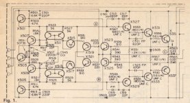
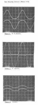
Sansui "Tanaka Non Switching" monitors the sum of Vbe of the last two power devices, plus the voltage drop that occurs on the 0.33 Ohm emitter resistance. This simple schematic seems to be effective as explained by Tanaka, the author of the design, in the AES publication he made in 1980.
AES E-Library: New Biasing Circuit for Class-B Operation
There are, however, some differences between the circuit that got described at the AES, and the practical implementation in the Sansui AU-D5 amplifier.
Don't know if there are practical Sansui implementations, closer to the circuit that got described at the AES.
See attached pictures.
Attachments
Last edited:
You are very welcome...has deep knowledge and wants to teach people
We are needing you urgently, as the ones knows more....here...are teaching less....keeping some advantage to themselves....in the reality, i think, they have not real knowledge, and do not teach us things to avoid us to discover they are empty inside.
I am glad you have "landed" here...... we need you.
regards,
Carlos
Excepting for design with diodes, others only work as advertised into resistive load.
A reactive load can source or sink away the reserve current, causing the affected
power device to still shut off sometimes.
I like Schottky diodes to moderate the crossing: square law curves, low dissipation,
and fast clean recovery. A resistor across the same fixed voltage span, but not in
any way connected to the load, draws the constant reserve current. The diodes
insure the load never has a path to source or sink away this reserve.
I slave the power devices to the curve of the diode crossing. I do not curve upon
the law of hot devices that may or may not always be well matched compliments.
Much easier to trust two cold Schottkys be our good quasi-complimentary match.
Last edited:
hello,
would there be an intellectual property infringement if a company sells three small PCBs, or carrierboards, about 1.5 by 1.0 inch tall, fitted with SMDs, ready to use, providing each one a specific Class AB biaising scheme :
- "New Class A" bias module (see Technics folklore - synchro bias)
- "Super-A" bias module (see JVC folklore)
- "Non Switching" bias module (see Pioneer folklore)
The idea is to help hobbyists designing their own audio power amplifiers, making an effortless revival of the three non-switching class AB biaising methods. Hobbyists and designers would integrate the module of their choice onto their own main board.
Technics "New Class A" is relying on fast diodes, implementing a dynamic switch that is automatically chosing between the voltage that's coming from the driver (this is when the output device is pushed to drive the load), and between a fixed voltage that is preset and defining the minimum bias current (this is when the output device gets pulled out, with the load being driven by the other half).
Looks fine, apart from the inherent switching nature of the process. Technics engineers used to call it "synchro-bias", but the marketing rejected that name, and coined "New Class A" for very understandable reasons. I guess that nowadays ultrafast diodes can be used, specified with a less than 10ns switching time, an order of magnitude faster than the output devices.
JVC "Super-A" monitors the sum of Vbe of all output devices, plus the voltage drop that occurs on the 0.22 Ohm emitter resistance. This voltage gets then compared to a fixed threshold (like 2 Vbe in case of a Darlington), and when the total voltage gets beyond this threshold, plus a little something, a transistor fitted into the Vbe multiplier arrangement acts to gently increase the multiplication coefficient.
Looks weird, like a positive feedback ! The increase rate must remain well controlled.
Pioneer "Non Switching" monitors the sum of Vbe of all output devices, plus the voltage drop that occurs on the 0.22 Ohm emitter resistance. This voltage gets then compared to a fixed threshold (like 2 Vbe in case of a Darlington), and when the total voltage gets beyond this threshold, plus a little something, a transistor fitted into the Vbe multiplier arrangement acts to gently increase the multiplication coefficient.
In essence, this is exactly as JVC "Super-A". Pioneer scheme needs a supplementary current source, which would make transistor count higher than JVC "Super-A", but on the other hand Pioneer takes some shorcuts regarding the Vbe multipliers, saving transistors over there.
What about the LT1166 ? It is an integrated circuit from Linear Technology specially designed for biaising Class AB amplifiers. Would be a 4th module welcome, embedding a LT1166 ?
Don't you think that with the advent of Class D audio amplifier, there will be some hobbyists wanting to confront Class D sound with some other (older) technologies, that one cannot find anymore, like those three fancy Class AB biasing schemes dating back from the early eighties, and possibly the LT1166 way also, which is more recent ?
thanks for taking the time for reading
all these approaches are attempts, to achieve the sound quality of the pure ClassA mode. until this day nobody has 100% success with this - so this is still a challenge.
Here you will find more such historical approaches:
http://www.bgaudioclub.org/uploads/docs/High_Performance_Audio_Power_Amplifiers,_B.Duncan.pdf
The only not pure classA amp with pure classA sound, that I know is the Yamaha HCA amp MX-10000:
http://www.diyaudio.com/forums/soli...lic-conversion-amplification-hca-circuit.html
Pioneers approach - "New Biasing Circuit for Class-B Operation" - the patent:
Patent US4476444
The making of an effortless revival from all non-switching class AB biaising methods is indeed an interest idea for the aim of evaluation. Perhaps anybody realize this and offer such an evaluation amp kit.
Last edited:
Far as I know: The easiest way to assure operation in this class is to cross
deliberately underbiased Schottkys. Thus forcing them to operate upon the
square law curve. You then use this law to re-curve your power transistors
for a super-smooth B crossing! Plus the reserve current always bled by R1.
It doesn't matter that Schottkys operate in Class B and turn off. There is
no significant tail current, and they recover fast. The slow transistors are
always conducting the reserve current, and thus in Class A at all times.
It doesn't matter the exact quiescent current of an underbiased Schottky
B crossing. Its always more than zero, and less than would blow anything.
Will probably drift a bit with temperature. You can bond Q3 Q4 to heatsink
if you want to assure hot drift always floats deeper into B rather than AB...
It probably isn't necessary.
Remember: We are talking about a deliberate underbias. No more than one
half the Schottky stack can ever be fully on at once. We strictly regulate
the voltage sum across the stack, so that could never happen. Runaway
just isn't a likely event, even if you did nothing to thermally compensate.
Whats a Schottky diode gonna dissipate in this application? Less than 2W.
TO-220 packages are common, so thermals are going nowhere! Hot power
devices only do the work, but are never trusted to make the decisions.
The smoothness of the crossing is assured by the quasi-complimentary
square laws, and not by a specific bias current that has to be controlled.
No attempt is made to define what actual small B crossing current might
be? The extra reserve current bleeder assures the power devices will be
operating well above the small crossing of the Schottkys.
Attachments
Last edited:
Wow, that looks truly impressive Kenpeter - dirt cheap and dirt simple. I like it. Do you have any practical measurements/builds to share with us?
Thanks
Thanks
Last edited:
This patent is not about the non-switching stuff. It is about the dual amp using floating supplies, same approach as Technics Class A+.Pioneers approach - "New Biasing Circuit for Class-B Operation" - the patent:
Patent US4476444
I have two questions :
1) Is there a patent infringement in case one manufactures complete non-switching power amplifiers or tiny bias sub-assy boards working as described above : Technics New Class A (Synchro Bias), JVC Super-A, Pioneer Non-Switching, or Sansui Tanaka Non-Switching ?
2) Is there a patent on the Sansui Tanaka Non-Switching technique presented at the AES ?
Thanks,
Steph
At fisrt glance, the Ben Duncan books looks quite general. Digging into the individual chapters, the big and positive surprise is to realize how precise and accurate Ben Duncan is. The appendixes are unvaluable, plenty of references, plenty of historical info. Many many thanks for pointing this great source of info !Here you will find more such historical approaches:
http://www.bgaudioclub.org/uploads/docs/High_Performance_Audio_Power_Amplifiers,_B.Duncan.pdf
Page 133, about the non-switching amplifiers, it reads :
"This involved a kind of positive feedback, and carrying the risk of blowing-up the output stage ! It also relies on the switching of small diodes, which ameliorated and displaced, rather than overcoming the switching problem".
I guess Ben Duncan didn't wanted to write explicitely that the Technics SynchroBias, marketed as "New Class A", was displacing the problem instead of solving it. The Technics "New Class A" is thus a little bit apart. It should be clear and remembered that JVC "Super-A", Pioneer "Non Switching" and Sansui "Tanaka Non-Switching" are not relying on diodes to be switched.
It is amazing to see the LT1166 biasing integrated circuit, being ignored. Were there commercial power amplifiers using a LT1166 biasing integrated circuit ?
Like Margan, what's worrying me is the behaviour of the output stage when driving a complex load like a loudspeaker. Some optimizations like the ones discussed here may prove unable to cope with capacitive, inductive, or varying impedance loads, especially on non-periodic, non-static, non-symetric input signals like music is. In this context, is there a LTspice standard test gig I can use, for better knowing the behaviour of the output stage ?
Cheers,
Steph
Last edited:
This patent is not about the non-switching stuff. It is about the dual amp using floating supplies, same approach as Technics Class A+.
I have two questions :
1) Is there a patent infringement in case one manufactures complete non-switching power amplifiers or tiny bias sub-assy boards working as described above : Technics New Class A (Synchro Bias), JVC Super-A, Pioneer Non-Switching, or Sansui Tanaka Non-Switching ?
2) Is there a patent on the Sansui Tanaka Non-Switching technique presented at the AES ?
Thanks,
Steph
Yes, you are right.
Regarded your first question it is for me in generall the problem to find the right google-keywords, because for the same amplifier idea/topology there are much different names resp. terms. If I don't know all terms therefore, it is impossible, to find all exist informations (sometimes only about chance).
Regarded Sansui's developer Mr. Tanaka I found about
Sansui Au111 [Archive] - AudioKarma.org Home Audio Stereo Discussion Forums
in post from BeatleFred (01-26-2003, 12:14 AM) informations concerning an AES (JAES) article, unfortunately without the exact title of this paper. But perhaps this information is useful for an additional websearch.
The LT1166 is an advice, that is very good for servo biased topologies (and new for me). Unfortunately I don't know commercial amplifiers, where this IC is inside. And I haven't never heard an amplifier inside this servo.
Here some ULRs therefore and some discrete servo bias/automatic bias topologies:
http://www.diyaudio.com/forums/solid-state/173-anybody-played-self-class-bias-regulator.html
http://www.diyaudio.com/forums/solid-state/1573-linear-tech-lt1166-chip.html
http://www.diyaudio.com/forums/soli...amplifier-automatic-variable-bias-system.html
ÃÈÁÐÈÄÍÛÉ ÓÑÈËÈÒÅËÜ
http://www.diyaudio.com/forums/solid-state/40877-n-channel-mosfet-amplifier-servo-bias.html
http://www.diyaudio.com/forums/solid-state/26043-thermistor-use-power-amp-bias-servo-circuit.html
http://www.diyaudio.com/forums/tubes-valves/25506-push-pull-bias-servo.html
for the death link there go to
Gary Pimm's DIY audio pages
Auto bias circuit for power amplifier using power MOSFET - Patent 6683500
Patent US4160216
Madrigal Library: Adaptive Bias
http://www.freepatentsonline.com/3995228.pdf
http://www.hagtech.com/pdf/vbe.pdf
Last edited:
专利
早在一年前这线路做成功了,现在已经获得中国专利。你这线路含有专利的一部分。far as i know: The easiest way to assure operation in this class is to cross
deliberately underbiased schottkys. Thus forcing them to operate upon the
square law curve. You then use this law to re-curve your power transistors
for a super-smooth b crossing! Plus the reserve current always bled by r1.
It doesn't matter that schottkys operate in class b and turn off. There is
no significant tail current, and they recover fast. The slow transistors are
always conducting the reserve current, and thus in class a at all times.
It doesn't matter the exact quiescent current of an underbiased schottky
b crossing. Its always more than zero, and less than would blow anything.
Will probably drift a bit with temperature. You can bond q3 q4 to heatsink
if you want to assure hot drift always floats deeper into b rather than ab...
It probably isn't necessary.
Remember: We are talking about a deliberate underbias. No more than one
half the schottky stack can ever be fully on at once. We strictly regulate
the voltage sum across the stack, so that could never happen. Runaway
just isn't a likely event, even if you did nothing to thermally compensate.
Whats a schottky diode gonna dissipate in this application? Less than 2w.
To-220 packages are common, so thermals are going nowhere! Hot power
devices only do the work, but are never trusted to make the decisions.
The smoothness of the crossing is assured by the quasi-complimentary
square laws, and not by a specific bias current that has to be controlled.
No attempt is made to define what actual small b crossing current might
be? The extra reserve current bleeder assures the power devices will be
operating well above the small crossing of the schottkys.
The Sansui Tanaka patent is US4401951. It also has the discussion of a few other "nonswitching" patents.
The common mistake with this approach is to leave Power stage with the new type of distortions due to unpredictable nonlinearity of P. transistors currents at the small levels (and near the signal zero crossing!).
The common mistake with this approach is to leave Power stage with the new type of distortions due to unpredictable nonlinearity of P. transistors currents at the small levels (and near the signal zero crossing!).
Member
Joined 2009
Paid Member
I spent some time researching non-switching outputs and found there are quite a few techniques, as already mentioned. I went as far as simulating a few designs to see that they do in fact work as promised.
But I didn't build any - I was not convinced that the additional complexity would result in an improved listening experience.
Has anybody listened to one of these non-switching designs, even an old Sansui, and compared it with a good 'regular' type Class AB amplifier ? - if so what did you discover ?
Yes, sort of 😀 I say sort of because i built a few amplifiers based on the original Technics design that used an output stage that was fully biased into class A & ran at a low voltage.Has anybody listened to one of these non-switching designs, even an old Sansui, and compared it with a good 'regular' type Class AB amplifier ? - if so what did you discover ?
The idea was you have a standard class B or AB amp drive the floating ground of the low voltage class A stage & the output of the class A stage was connected to the speaker. Therefore any or should i say most of the distortion produced by the AB amp would be corrected by the class A amp simply because the A amp is also in the feedback loop. In my case the A amp was unity gain so had it's own feedback to correct any problems. Open loop gain of the front end of the amp was about 400 & closed loop was 20. The result was as good as a true class A amplifier, though i used a few tricks like nested differential feedback loops. I doubt it needed that though.
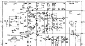
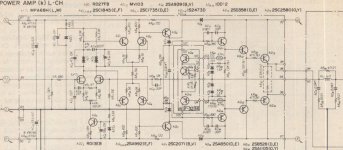
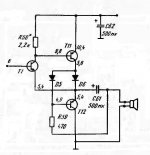
I will show one "well forgotten" circuit from the '60s with the interesting properties.
It is SRPP (in Cl. A bias), but is Non-Switching in Cl. AB bias.
T11 will never switch off. The Non-switching condition for T12 is
V(D5)≥0.5V + V(D6)max.
D6 should be Schottky (to minimize power waste) with the appropriate current rating and in TO-220 or TO-3P case.
Obviously, it is the voltage follower/power buffer and T1 provides the Error Correction function for Pushing and Pulling action of T11, T12.
The bias with the shown values: T1, T12 ~0.4 mA, T11 ~10 mA, D6 is (may be) non conducting. D5 is generally not necessary (only for non-switching T12 and Cl. A bias) and can be shorted. C61 provides bootstrapping for R59.
The circuit can be easily modified for bipolar supplies and scaled for the higher voltages/power.
And now you can explore the quietly ignored "new" idea along these lines from Andreas Wahlberg :
http://www.diyaudio.com/forums/solid-state/21329-self-regulating-class-2.html
espacenet — Bibliographic data
Attachments
Last edited:
早在一年前这线路做成功了,现在已经获得中国专利。你这线路含有专利的一部分。
Automaticly translate: A year ago to do this line a success, and now has received patents in China. You are part of this line with the patent.
what means this exactly?
This the famous Nelson Pass patent, indeed. Thanks 1000 times for reminding us. It is panicking to see those japanese companies (Matsushita, JVC, Pioneer, Sansui) rushing around 1978-1979 for Non-Switching Class AB, while Nelson Pass had it done as soon as Feb 1975, with his US patent granted Nov 1976. What are the commercial amplifiers made, and what are the DIY amplifiers made, using Nelson Pass schematic ?
Kenpeter, to change the bias to Cl. A, select D5 to produce higher voltage
drop ~1...1,2V (IR diode, or voltage multiplier) to produce
V(D5)=0.8V(VbeT12) + 0.2V(Schotk. D6),
and reduce R58, R59, to accomodate the bias currents in all transistors, using corresponding betas (current gain).
In class A both diodes will always conduct. That is SRPP.
D5 will conduct in all modes/time.
In cl. AB D6 does not have to conduct when T12 is supplying the current in it's half cycle.
Member
Joined 2009
Paid Member
the schematic posted looks like it was extracted from a patent. The purpose of a patent is to say just enough to get ownership of the IP and avoid saying what is necessary to actually make the darn thing.
- Status
- Not open for further replies.
- Home
- Amplifiers
- Solid State
- New Class A, Super-A, Non-Switching : need a revival ?