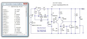
R8=R9 between 500r and 700r.
remove R2.
Return R10 to 4k7
2mA through R10 should then be split into 1mA through each of R8 & R9.
The Vbe of Q2 forces ~1mA through R9=600r.
remove R2.
Return R10 to 4k7
2mA through R10 should then be split into 1mA through each of R8 & R9.
The Vbe of Q2 forces ~1mA through R9=600r.
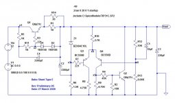
Zen Mod said:10n to 100n across R12
I added 10uF.
And, did other things too . . . 😉
>🙂<
Attachments
Babowana said:
I added 10uF.
And, did other things too . . . 😉
>🙂<
no uF (1x10^-6F)
but nF (1x10^-9F)
that's for decreasing gain of stage in highest freq - better stability

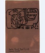
And, this is my thinking about what I would like to go with.
The board size is 110mmx170mm, on which all will be arranged including transformer and aluminium heatsink (just a flat plate) for TIP TRs. And, I'm thinking whether I should have a power switch or not. Another already built Type A has no power switch (24hour on) tho . . .
>🙂<
The board size is 110mmx170mm, on which all will be arranged including transformer and aluminium heatsink (just a flat plate) for TIP TRs. And, I'm thinking whether I should have a power switch or not. Another already built Type A has no power switch (24hour on) tho . . .
>🙂<
Attachments
Babowana said:Thanks, ZM!!!
By the way, you never sleep . . . ???
>🙂<
little Isa have heavy flu ..... so - it's sorta easier not to sleep and take care about regular medications and wet bandages , than to jump from bed each hour or two ....
besides that - my back still feels nervous , so I'm nervous ....... finding right position in bed is dreky task , if you must repeat it every hour or two .
😉
I already know that I'll sleep half of day ....... soon

AndrewT said:Hi Babo,
do you want/need any of my advice?
Yes. Thanks.
But, I also want to consider my own small knowledge.
I would like to have a diff amp of ac voltage gain as high as possible. Please save me. Why the reduced sizes of R8 and R9 are adviced?
Regards,
>🙂<
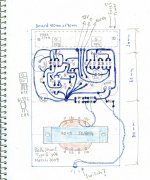
the routing of the bridge rectifier must be changed.
The AC connects to the bridge.
The +ve output and the -ve output must go straight to the smoothing cap. No other tappings off these traces. Keep them very short and keep them close together to minimise the loop area of the charging circuit.
Then feed the rest of the circuit from the +ve and -ve of the smoothing cap.
DO NOT take the bridge rectifier to the star ground.
This route :- Transformer secondary to rectifier to smoothing cap and back again through the rectifier to the secondary, carries high current short duration pulses. These pulses WILL create pulsing voltages on the traces. Do not contaminate the star ground with these pulsating voltages in the cap recharging circuit.
AndrewT said:
DO NOT take the bridge rectifier to the star ground.
This route :- Transformer secondary to rectifier to smoothing cap and back again through the rectifier to the secondary, carries high current short duration pulses. These pulses WILL create pulsing voltages on the traces. Do not contaminate the star ground with these pulsating voltages in the cap recharging circuit.
Good comment. I like it.
In principle, mine is arranged as you say, except that I take the bridge to the star ground. Sure that the bridge is touching the star ground, but not by-passing any other ground loop to go to or come from the smoothing cap. So, the other loops don't see the pulsing voltage. Don't you think so?
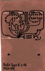
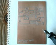
Anyhow, I have already finished my PC board . . . and in somewhat special way different from my original PC board plan. Tomorrow, I will show you.
>🙂<
look at that smoothing re-charging route.
The -ve of the bridge rectifier to the star ground to the -ve of the smoothing cap.
This route carries pulsing currents.
The length of trace from star ground to -ve cap will have a pulsating voltage from end to end.
If the cap is doing it's job it holds a constant voltage. The star ground WILL vary relative to the -ve of the cap.
That is noise where it can be very easily avoided.
- Status
- Not open for further replies.
- Home
- Amplifiers
- Pass Labs
- New-building of my B1 buffer