I've seen fairly decent arguments for use of shunt regulators in circuits that effectively draw DC, but they're based on waste (or not, as the case may be) of power, not sonics. Supposedly the converse arguments favor series regulation for circuits that have varying draw.
I'm an agnostic, myself.
Grey
I'm an agnostic, myself.
Grey
my reason is most superior one , and strictly non debatable :
I like Neon Toobz ;
tiny zenners are for sissies .

I like Neon Toobz ;
tiny zenners are for sissies .
Zen Mod said:my reason is most superior one , and strictly non debatable :
I like Neon Toobz ;
tiny zenners are for sissies .
And to scare more off...some use radioactive isotopes too!😀
''Gas discharge tubes require some stimulus to initiate the ionisation process. Most of the data sheets for the types listed below specify a certain level of incident light that is required to ensure ignition at the stated voltage. The 150B2 data sheet I found gave two ignition voltages, one for a specified range of ambient light and another, higher voltage, for operation in total darkness.
Note: Some older military parts have small internal radioactive sources to initiate ignition in total darkness! These valves are potentially highly dangerous and professional help should be sought if they are identified. These should be marked with the normal triangular radioactivity symbol.'' Andrew Burge, MOBXT site.
Naah! What is not to like?
P.S. Bcs of your expected ''pink'' Zener user comment, I chose to use a ring of two BJT Isource feeding a resistor Vdrop reference in my Mosfet HV shunt. So I passed only with an ''Ugly
 ''TM comment from you
Attachments
Hi Babowana,
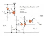
Q3 base reference voltage is to high, the diff pair emitter voltage should be less than 4v so you can control the shunt FET Q5.
Like 3.5v at the emitters and a 4.2v reference at Q3 base. R12 10k R13 3k
Q3 base reference voltage is to high, the diff pair emitter voltage should be less than 4v so you can control the shunt FET Q5.
Like 3.5v at the emitters and a 4.2v reference at Q3 base. R12 10k R13 3k
Hi, Leapcat
Thank you very much. I have thought the same during my 7th chemo treatment. Before I change the circiut (type B) with your values, however, I would like to try the following type A first.
Hi, Salas
I like your method on post #156 and Juma's on post#157.
Nevertheless, could you kindly simulate the followwing type A for me? Thanks.
>>🙂<<
It seems that two more chemo left . . . and 🙂 . . .
Thank you very much. I have thought the same during my 7th chemo treatment. Before I change the circiut (type B) with your values, however, I would like to try the following type A first.
Hi, Salas
I like your method on post #156 and Juma's on post#157.
Nevertheless, could you kindly simulate the followwing type A for me? Thanks.
>>🙂<<
It seems that two more chemo left . . .
and 🙂 . . .Attachments
Babowana said:Hi, Salas
I like your method on post #156 and Juma's on post#157.
Nevertheless, could you kindly simulate the followwing type A for me? Thanks.
>>🙂<<
It seems that two more chemo left . . .
Hello, best wishes for health! Did your sim, also tried leapcat's suggestions (4V3 Zener, R13 3k), too little ouput voltage in both cases.
Attachments
Salas,
Q5 is wrong, it should be Pchannel.
Did you ask the sim to tell you the Vgs of the FETs?
Do this for the schematic posted and for the next where Q5=Pchannel.
I think you'll find that 10k collector loads are far too big, forcing the LTP to run unbalanced. You must have the correct Vgs on the FETs.
I think R7 should be raised ~4k7 or 5k1.
Did it with Q5 IRFP9240. It will not open, 0.5V VGS. Q1 works with 3.14V VGS. Same 0.5V for output. With Q5 NFET 240, gives 3.236V VGS as in the last sim pic.
what currents are flowing in R6, R8 & R11?
You would all be far better, far quicker and learn far more if you put the simulators back on the shelf and generate a working shunt reg manually, either by calculation or by inspired guesswork at the bread board.
Then, analyse the performance of the working shunt, using your beloved simulators.
You would all be far better, far quicker and learn far more if you put the simulators back on the shelf and generate a working shunt reg manually, either by calculation or by inspired guesswork at the bread board.
Then, analyse the performance of the working shunt, using your beloved simulators.
is that Vgs or Vgd?salas said:With Q5 NFET 240, gives 3.236V VGS as in the last sim pic.
similarly when you put in the Pchannel, what did you measure?
they are your problem.salas said:The simulators aren't a problem, if I have thought of my own circuit. They just help to check fast.
R7~-4k7 to 5k1.
R8~=3k0 if 1n4739=9.1V
But, replacing R8 with a 2.8mA CCS and then trimming the collector load to give the 9.1V on the bases of the LTP.
AndrewT said:is that Vgs or Vgd?
similarly when you put in the Pchannel, what did you measure?
Why are my problem? Its Babos design. And the last one works, after I put the mosfet right. VGS=3.2V.
- Status
- Not open for further replies.
- Home
- Amplifiers
- Pass Labs
- New-building of my B1 buffer