Hi all. A few years ago I built a pair of full range column speakers using a pair of Alpair 7.3's. The folks who bought them want a smallish sub to match so I've been working on this lately.
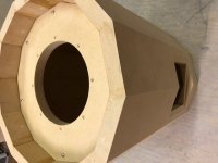
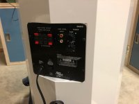
This image shows what it will look like when done. It's downfiring GRS 8SW-4 8" driver, powered by a Dayton SA25W plate amp in an enclosure of 1.281 CF. I've gone in that direction for size constraint as it's going into a small house.
I'll post some fabrication pics next time around.
Regards John L.
Last edited:
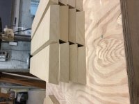
Here's the next step. The staves have to be cut with the correct angle and to length. This is the most critical step as any variation in width or angle will create problems with assembly.
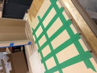
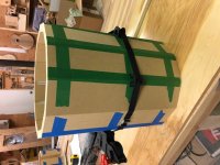
The staves were laid flat on their small sides with the top edges touching and square. At this stage I used masking tape across the six staves to hold them together. Then I taped each joint which acts as a seal and hinge. This polygon has twelve sides and I had six staves per assembly. This was as much as I could practically flip over. Once flipped over and the staves are on their wide sides, glueing can be done. Make sure there's enough glue to cover each face but not too much that it resists mating the angle faces. When the two halves were rolled up, then I used a strap clamp to keep them together while the glue dried.
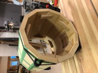
When the two halves were dry, I then attached cleats to the inside for future fitting of the baffle and top. This also adds strength to the joints. The cleats were glued and screwed. The final part of this stage of assembly is to glue the two halves together.
Regards John L.
The staves were laid flat on their small sides with the top edges touching and square. At this stage I used masking tape across the six staves to hold them together. Then I taped each joint which acts as a seal and hinge. This polygon has twelve sides and I had six staves per assembly. This was as much as I could practically flip over. Once flipped over and the staves are on their wide sides, glueing can be done. Make sure there's enough glue to cover each face but not too much that it resists mating the angle faces. When the two halves were rolled up, then I used a strap clamp to keep them together while the glue dried.
When the two halves were dry, I then attached cleats to the inside for future fitting of the baffle and top. This also adds strength to the joints. The cleats were glued and screwed. The final part of this stage of assembly is to glue the two halves together.
Regards John L.
Attachments
I don't know why those pics are sideways. When I previewed the post the displayed correctly. Anyone have any ideas?
John L.
John L.
No I don't.Looks great.
Do you have any sims?
I used the recommended volume for the enclosure.
I don't have any software to simulate.
Regards John
No I don't.
I used the recommended volume for the enclosure.
I don't have any software to simulate.
Regards John
There are many free programs that will do this...
Thanks, I'll take a look.There are many free programs that will do this...
John

This looks awesome! Looking forward to seeing the final build.
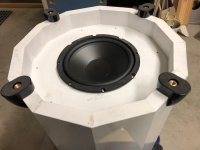
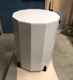
Thank you. I'm pleased with the visual result. The fact that I used a budget driver shows though. It's ok as my friend had limited funds to put into the project and really wanted the shape the same as the speakers I had made a few years ago so (that) part of the project was satisfied. We can upgrade the driver at a later date. I'm considering a Dayton DCS205-4 8". Anyone had any experience with this model? I cut double the number of wood parts so I will now build another when I return from vacation for myself. I haven't yet decided on the driver for it yet.
Season's greetings all.
Attachments
A few things:
1. With a twelve-sided enclosure like that, I might've opted for three legs instead of four on the bottom. That way all of the legs will always be in full contact with the floor. For four legs to do that, the floor will need to be perfectly flat.
2. I've used the Dayton DCS205. 1.2. cu.ft. is a bit large for it, particularly for a sealed alignment. I'd opt for one of the larger drivers and make the mounting hole a bit larger to accommodate it.
- Home
- Loudspeakers
- Subwoofers
- New budget subwoofer