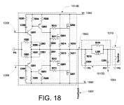
Looks like a couple of CFP emitter followers driving a couple of MOSFET source followers. In your opinion, what's the numerical value of gain? 0.999x?Page 18 is the output stage. It has gain and it's own feedback loop.
Very Brystonian, aligned with their problematic compound bipolar output topology.Page 18 is the output stage. It has gain and it's own feedback loop.
Looks like a couple of CFP emitter followers driving a couple of MOSFET source followers. In your opinion, what's the numerical value of gain? 0.999x?
It could be almost anything 1 or above depending on the resistors chosen, which aren't shown in the diagram. I would assume however that it would at least be large enough to overcome the 4V penalty of the cascoded VAS (one good reason to use an output stage with gain).
Attachments
Last edited:
Here is the simulation with a plain Lfet output stage since I don't want to spend all day guessing the values for the original OPS. However the intended OPS would probably reduce distortion to levels similar to those claimed in the patent (Even the measurements are just LTSpice FFT charts!)
I have done the bare minimum required to stabilize it, but it's still probably far from optimal.
I have done the bare minimum required to stabilize it, but it's still probably far from optimal.
Attachments
Last edited:
You can get a much more legible copy of the patent from pat2pdf.org.
Does anyone actually know what EXACTLY they are patenting?
Does anyone actually know what EXACTLY they are patenting?
Input filter topology?You can get a much more legible copy of the patent from pat2pdf.org.
Does anyone actually know what EXACTLY they are patenting?
IMHO a typical US hot air patent - full of prior art.
The oddest part for me at first glance: why on earth does he return the input PNP collectors to the current source?
All I know this has prior art back to at least 1968
(Barry Blesser's "super" transistor).
I don't think this is "super pair" or CFP pair. I think that each amplifying device is isolated by emitter follower here.
Attachments
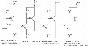
I don't think this is "super pair" or CFP pair. I think that each amplifying device is isolated by emitter follower here.
That make sense. Once the emitter follower turns on, the impedance at the output of the LTP becomes very low. The question is why?
curiosity did get the best of me. I print out the patent and at least read through the diagrams and their description. It is a patent of the whole amp, not the front end. Other than the front end, it is just some variation of a typical amp to me. What notch filter, summation and all?
I think the guy spent the money to get a patent just to say he has a patent. Good luck in enforcing any of that.
I think the guy spent the money to get a patent just to say he has a patent. Good luck in enforcing any of that.
The input topology is reminiscent of some balanced mic preamp inputs, e.g. P66 - and I think it wasn't exactly new when Rod Elliott did this back in 2000. Here they just added some emitter degeneration for the input transistor for better linearity, which you obviously wouldn't do on a mic preamp.
I'm not sure why CFP inputs aren't more common, actually. Shouldn't they improve gm nonlinearity? Sure it adds extra poles, but so does a 2-stage differential circuit. Current sources would also be running at higher current, so I guess CMRR wouldn't be quite as good.
I'm not sure why CFP inputs aren't more common, actually. Shouldn't they improve gm nonlinearity? Sure it adds extra poles, but so does a 2-stage differential circuit. Current sources would also be running at higher current, so I guess CMRR wouldn't be quite as good.
anything feeding input directly onto a supply rail is a old or bad design common in cheap radios from the 70's.
A good amp has a split supply and 0v differential input
A good amp has a split supply and 0v differential input
It's an "everything and the kitchen sink" style patent. I am sorry, though, that the inventor left us so soon.curiosity did get the best of me. I print out the patent and at least read through the diagrams and their description. It is a patent of the whole amp, not the front end. Other than the front end, it is just some variation of a typical amp to me. What notch filter, summation and all?
I think the guy spent the money to get a patent just to say he has a patent. Good luck in enforcing any of that.
When one inspects an overall topology for error sources, one must take into account the often greatly-increased voltage and current swings with signal in successive stages. It may often turn out that concern over the specifics of the input stage is misplaced, although noise considerations are always important.
If you are willing to spend lots of power in the feedback network by making its impedance low, and use the inverting mode overall to make common-mode errors small, the input stage can be very simple and still yield excellent results. The second stage is much more important if the traditional transconductance-with-local-feedback approach is used. And the output stage performance is always of significance.
There are reasons why CFPs are not used everywhere. It's instructive to play with those to see where the parasitic poles start to make overall global feedback tougher to achieve stability.
And as Dimitri opines, and I agree, these are not really CFPs anyway.
Component values are given for the frontend in balanced and unbalanced versions, but not the output stage.
One additional cavil: a simulation result concerning distortion is cited as amounting to a determination of signal-to-noise ratio.
Another oddity is the paralleling of output devices is cited as also being better for signal-to-noise.
Confused.
Another oddity is the paralleling of output devices is cited as also being better for signal-to-noise.
Confused.
Good catch. I'm surprised by how many people don't understand simulation and noise analysis.
But notice that in the amp owner's manual realistic distortion and SNR numbers are given. It seems a lot of people misuse simulators to produce unbelievable numbers, and then when the circuit doesn't match the simulation they say "well, simulation always gives better results than real life".
But notice that in the amp owner's manual realistic distortion and SNR numbers are given. It seems a lot of people misuse simulators to produce unbelievable numbers, and then when the circuit doesn't match the simulation they say "well, simulation always gives better results than real life".
Hi Guys
Talk about missing the boat!
Patents typically show representative circuits not necessaarilly those used in production. If the original poster bothered to trace out the circuit in his "Cubed" amp he would find something quite more typically Bryston and far unlike that in the patent.
The patent refers to notch filter designs from quite a few years ago. I believe the point of the application here is to greatly reduce the artifacts related to mains noise intrusion, not just of fundamtentals but mainly in reducing those of IM. Bryston has paid great attention to layout and has been a huge promoter of balanced connections between audio equipment. Their larger PAs are all balanced designs with a "double-balanced" input stage (my term) and the patent shows such topologies in the many drawings. The drawings do not show all of the choices and techniques used to achieve best linearity.
Salomie's affection for mosfets in the audio path is not shared by Bryston. To the poster above who decided not to buy a Bryston amp based on his misinterpretation of their schematics, it is a shame for you. Schematics do not reveal everything about a circuit - just the topology. Certainly if you sim their DOA, for example, THD is higher than if you add the EF for the VAS stage but what are the other consequences of that? Bryston's preamp THD is unmeasurable by the latest Audio precision system.Bryston's Quad-Complementary output stage is far from unstable or problematic - I have used it in many amps over the years and it works extremely well with all loads, plus it is very simple to add protection to as Bryston's schematics show.
Bryston has not released the schematics of the new amps yet. When they do you will see what is really going on. Until that happens all the above is pointless conjecture.
Have fun
- Status
- Not open for further replies.
- Home
- Amplifiers
- Solid State
- New Bryston input stage measurable distortion < 0.001% (Audio Advisor)