If I can find it I will post. Richard Marsh also did an MC stepup with common base devices and that was in an ancient copy of Audio Amateur.Sure, but I would appreciate a link to it, because I do not know the title of the article.
Brad
I found an article about some of his phono preamps here: Moving Coil Cartridge Head AmpsIf I can find it I will post. Richard Marsh also did an MC stepup with common base devices and that was in an ancient copy of Audio Amateur.
Brad
Hi Guys
My turn to be confused:
Dadod wrote: "Loop Gain plot (feedback)"
The word "loop" suggests that the feedback loop is intact, so really "closed-loop gain". If the roller coaster plots are OPEN-LOOP, then that should be called something else, such as "open-loop gain".
Have fun
There are three different plots, Open Loop gain, Loop Gain (how much feedback was used) and Closed Loop Gain. The Open loop gain you get adding the loop gain to the close loop gain. A Loop Gain is most useful as you can see a feed back value, a phase margin and a gain margin. In my opinion Loop Gain naming is confusing as a feedback loop does not have gain.
I always post a Loop Gain (LG) and Closed Loop Gain (CLG) for my amps, but not always in the same post.
If you have Cordell's book there is all that explained much better.
Yes - just adding to what Damir just said, the Loop Gain plot is always the most interesting one, as you can see the phase and gain margins and assess the amplifier stability with the loop closed.
In high-OLG designs, it's difficult to keep the amp stable with single-pole compensation, so two-pole or multi-pole compensation is used - that's where the roller-coaster comes from.
I prefer keeping the global loop gain relative low, controlling the local gain (and to some extent - linearity) of each stage under control with appropriate local feedbacks. This approach allows using single-pole compensation, keeping the distortion level low enough and allowing excellent transients handling and good closed-loop phase response at the same time.
Alas. As they say in Russia: на самом деле всё иначе, чем в реальности - it is actually different than in reality. 🙂I prefer keeping the global loop gain relative low, controlling the local gain (and to some extent - linearity) of each stage under control with appropriate local feedbacks. This approach allows using single-pole compensation, keeping the distortion level low enough and allowing excellent transients handling and good closed-loop phase response at the same time.
While you are building the amplifier in the imagination or on paper, everything is fine. The main speculative argument of the supporters of the multi-loop feedback that then the main loop covers already linear, thanks to the local loop, cascades and there is a benefit in the resulting linearity.
But as soon as you try to reconcile between the two or more feedback loops, you notice that with a decrease in the gain of some part of the amplifier and increase its linearity, increases the differential input voltage. This voltage is a much more important factor, one of the two factors, determining the linearity of the input stage and of the amplifier. The fact that the distortion of the input stage are directly dependent on the differential voltage, and cannot be corrected by feedback, because the cascade needs to be a reference.
In addition to the deterioration of linearity, multi-loop feedback leads to big problems in time of the input of the amplifier in the overload mode and limit the output voltage. Flash RF generation arising because of competition of cascades with local feedback loops, you have to calm down using compensating capacitors elephant capacity. Total for little money we have two unsolvable problems: with linearity and stability.
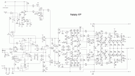
I saw the practical consequences of these two different approaches to the design of amplifiers. Amplifier "Natalie" has two loop feedback: General through R22R25-R28R29R30 and local R41R48-R42R49. The author complained about repeated outbreaks of RF generation, which is necessary to increase capacity correction С22С23, С24С26, С29С30 that reduces the depth of feedback and at 20 kHz it is impossible to achieve linearity better than 1 ppm.
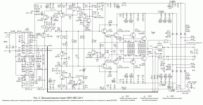
In the circuit of the next amplifier uses one common feedback loop and, in addition, the output stage of the voltage amplifier made under the scheme with a common base. This gives the advantage of stability, loop gain and linearity - 0.000.3% vs. 0.001%. And, mind you, the capacitance of compensating capacitors 10 times smaller, their number is also less, and the frequency compensation setup is much easier - practically, it's not needed.
Attachments
Last edited:
ANY amplifier utilises many local feedback loops. Any emitter degeneration is a local feedback. Example - emitter resistors in LTP. You increase the values - lower gain, less distortion (locally). Another example - resistor in VAS emitter. There are many others. So - arranging the right voltage gain distribution between the cascades, allowing optimal signal levels for each stage (remember - regardless of the way your global feedback loop is arranged, amplifier always works open loop).
Nested feedback loops is a completely different story. However, even in this case, it is possible to arrange the loops in a way that differential input voltage will not be increased.
The main question - WHY do you need nested loops? In my case, it was not to reach the minimal distortion, but to increase the output impedance of the amplifier to certain level - this made the amp sounding better with some speakers (paradox, huh?).
"While you are building the amplifier in the imagination or on paper" - I always publish the live measurements for my designs. Never leaving them op paper.`
And I also have designs, where "the output stage of the voltage amplifier made under the scheme with a common base" - this is a very good approach, as well as the arrangement of VT1 and VT2 in your amp, forming altogether a complementary differential circuit with the top input grounded (base of VT2).
Distortion level can be decreased even further if you use a non-switching of error-correction output stage - worth trying.
Cheers,
Valery
Hi!
Yes, a lot of them. But common between them is that the maximum gainwith open loop of the all cascades in them is of ultimate importance, therefore, any increase in the depth of the local feedback leads to a weakening of General feedback, the growth differential voltage and resulting distortion.
This can be seen in a good sim.
For example, one kind of local feedback loops is frequency compensation Miller. We all know that its use degrades the linearity of the amplifier.
Although, it would seem that the linearity of the amplifier is affected by this feedback, should rise precisely in the band of this feedback. Paradox? I don't think so.
ANY amplifier utilises many local feedback loops. Any emitter degeneration is a local feedback. Example - emitter resistors in LTP. You increase the values - lower gain, less distortion (locally). Another example - resistor in VAS emitter. There are many others.
Yes, a lot of them. But common between them is that the maximum gainwith open loop of the all cascades in them is of ultimate importance, therefore, any increase in the depth of the local feedback leads to a weakening of General feedback, the growth differential voltage and resulting distortion.
In fact, the same story. Only the view from the other side. Importantly, these small feedback loops devour depth General feedback. Always.Nested feedback loops is a completely different story.
The answer is no. The maximum gain for this circuit design is always a limit. No such local feedback loops, which would gain increased, and the differential voltage is reduced. The overall gain with the open loop - family capital. If you take this capital in the casino of Las Vegas, the family will be ruined. If you spend the total gain in the local feedback loops, always increases the differential voltage and the associated increase in distortion.However, even in this case, it is possible to arrange the loops in a way that differential input voltage will not be increased.
This can be seen in a good sim.
For example, one kind of local feedback loops is frequency compensation Miller. We all know that its use degrades the linearity of the amplifier.
Although, it would seem that the linearity of the amplifier is affected by this feedback, should rise precisely in the band of this feedback. Paradox? I don't think so.
Last edited:
OK, I'm not sure this kind of discussion is interesting to most of the audience. I'm not in "the best amplifier is the one having the lowest THD" camp, although most of my desighs are rather good performers in this area. OLG "as much as possible" - not my design approach 😉
I am adding a 6922 tube to my 5ppm mosfet amp as the tube sound is much more lifelike
low SS distortion will guarantee the tube distortion rules.
tube amps test like crap but sound much better if well constructed.
low SS distortion will guarantee the tube distortion rules.
tube amps test like crap but sound much better if well constructed.
- Status
- Not open for further replies.
- Home
- Amplifiers
- Solid State
- New Bryston input stage measurable distortion < 0.001% (Audio Advisor)