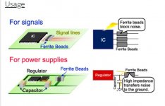
Put some ferrites right next to the OPamp inputs. Murata offers nice 0402 ones with 1k impedance. (Not the solution but will help somewhat)
The LM4562 is a bipolar input opamp and prone to RF EMI demodulation as seen here. Ferrites may/will help to improve PSRR here. If the input layout isn't well made (unsymmetric) things are getting worse.
Btw. have you monitored the opamps supply rail directly at the local decoupling cap?
hi doc🙂
how exactly should i implement the ferrits? input to gnd?
4562....the same result i get with the 49720
chris
Hi Turbowatch2
yes this amps sounds fine. the opamp is really fake. at the second amp the dimensions of the pins are too big that i have to fight to get out the DIL8 body...really😛
this was my intention to use a tpa3116 but in dual chip mode. if you want tot do some mods please report back. output filter to 10µH and other caps as i described.
chris
I've just received one of these and I've plugged it in to some Q Acoustic 2020 which are rated at 25 - 75W. I never considered that it might be over powered but I'm only using the first 20% of the volume dial before they're noticeably over powered.
Is there anything I can do to this amp or could someone recommend a similar amp with less power.
I do notice noise from the speakers when turning the amp up when nothing is playing..
Is there anything I can do to this amp or could someone recommend a similar amp with less power.
I do notice noise from the speakers when turning the amp up when nothing is playing..
I've just received one of these and I've plugged it in to some Q Acoustic 2020 which are rated at 25 - 75W. I never considered that it might be over powered but I'm only using the first 20% of the volume dial before they're noticeably over powered.
Is there anything I can do to this amp or could someone recommend a similar amp with less power.
The position of the knob does not say xx% of the maximum power is used. The problem is the gain, on some amps there are dip-switches to change it, on others you have to start up your soldering iron. I'm sure there are several solutions already here in the forum, search for 'tpa3116 gain'.
You could also put a voltage divider on the input or use a different potentiometer (ie. 100k instead of 20k?), the best solution is to reduce the gain though.
Hi tyler
yes ICG is right. at this amp you have to start to solder!-->SMD is a bit delicate to do it. open the amp, put out the board, remove heatsink...
its decribed at here - post 22: https://www.diyaudio.com/forums/cla...tpa3116-2-0-100w-dual-chip-3.html#post5791089
at the position where 104 resistor put in a 5600R=5k6R resistor smd and the other put out. data sheet table 6.5
chris
...efficiency...about 70-75%
Hi
i change on the amp 2 the output filter to the bourns and make some burn in with a sweep frequency 10-35k and an input voltage of 100mVrms. several hours. the gain is set to 20db.what i can say is that the heat sink is about 45°C and the coils about 48 °C😱 the lab power supply shows about 5W input power....the top case is open
if i am right the efficiency is not superb at this power level - home use.
datasheet figure 15 8R=75%,16 4R =72% and 23 2R=70%
so if you really want to push more power with this amp it will be better to drill some holes a the bottom and top case.
chris
The position of the knob does not say xx% of the maximum power is used. The problem is the gain, on some amps there are dip-switches to change it, on others you have to start up your soldering iron. I'm sure there are several solutions already here in the forum, search for 'tpa3116 gain'.
You could also put a voltage divider on the input or use a different potentiometer (ie. 100k instead of 20k?), the best solution is to reduce the gain though.
hi tyler
here is an illustration about input signal and output signal = gain
and what happened if the voltage get to the point of the max power supply (rail) voltage= clipping
Attachments
amp 2 changed outputfilter and opamp+ gain 20db
Hi
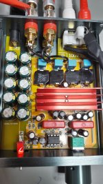
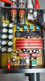
here are some pics with changed output filter 10µ Bourns SRP1250-100M at conrad shop about 1,83Euro each and fits perfect in this small housing. the output filter caps are TDK 0,68/100V. additionally i changed the gain to the lowest = 20dB=5,6kR. the opamp is the 4562. the origin was really fake because the dimension of the legs was unacceptable big that i have to push hard to get it out😡.
after 3 days burn in its a very good sound- i mean its near the tpa3250 (fx502spro). maybe the gain setting (20dB) is fitting best to this amp.i can say that the 4562 and the "better" coils(Bourns SRP1250-100M) fit very got together. opamp rolling will be done.
i report back.
btw...dont clean the coils with pcb cleaner...the printed label is gone 🙄😀
chris
Hi
here are some pics with changed output filter 10µ Bourns SRP1250-100M at conrad shop about 1,83Euro each and fits perfect in this small housing. the output filter caps are TDK 0,68/100V. additionally i changed the gain to the lowest = 20dB=5,6kR. the opamp is the 4562. the origin was really fake because the dimension of the legs was unacceptable big that i have to push hard to get it out😡.
after 3 days burn in its a very good sound- i mean its near the tpa3250 (fx502spro). maybe the gain setting (20dB) is fitting best to this amp.i can say that the 4562 and the "better" coils(Bourns SRP1250-100M) fit very got together. opamp rolling will be done.
i report back.
btw...dont clean the coils with pcb cleaner...the printed label is gone 🙄😀
chris
Attachments
Put some ferrites right next to the OPamp inputs. Murata offers nice 0402 ones with 1k impedance. (Not the solution but will help somewhat)
....
Hi Doc
As i look at murata i found that -pic
i will ordere these 0402 1k beats and try to find a place where i can solder this an report back
chris
Attachments
Hi doc
you asked for this:
Btw. have you monitored the opamps supply rail directly at the local decoupling cap?
i did it with my differential probe ...but i am not sure if that is correct/ok 😕
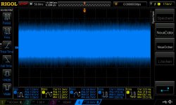
pic 1 pin 8 and pin4 amp on signal is a sweep 10hz-35khz with 100mVrms
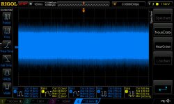
pic 2 pin 8 and pin4 amp on no signal
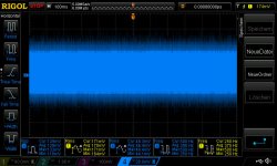
pic 3 pin 8 and pin4 amp on rca shorted
about 120mVpp is too much ??
chris
you asked for this:
Btw. have you monitored the opamps supply rail directly at the local decoupling cap?
i did it with my differential probe ...but i am not sure if that is correct/ok 😕
pic 1 pin 8 and pin4 amp on signal is a sweep 10hz-35khz with 100mVrms
pic 2 pin 8 and pin4 amp on no signal
pic 3 pin 8 and pin4 amp on rca shorted
about 120mVpp is too much ??
chris
Attachments
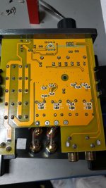
voltage at the opamp area
Hi
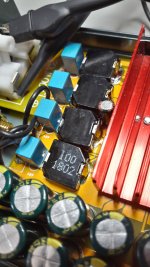
i did some DMM probes: the input is 24V from the power supply. a resistor divider set the op amp voltage to 22,87V.= 100k....only 1 rail cap(far away) is existing-blue circle.
10k resistors ......all yellow circles are build by this voltage divider 11,44V.
on the right corner the voltages sags to 11,35V
what schematic is that???😕
chris
Hi
i did some DMM probes: the input is 24V from the power supply. a resistor divider set the op amp voltage to 22,87V.= 100k....only 1 rail cap(far away) is existing-blue circle.
10k resistors ......all yellow circles are build by this voltage divider 11,44V.
on the right corner the voltages sags to 11,35V
what schematic is that???😕
chris
Attachments
Hi doc
you asked for this:
Btw. have you monitored the opamps supply rail directly at the local decoupling cap?
i did it with my differential probe ...but i am not sure if that is correct/ok 😕
How many differential probes do you have?
How many differential probes do you have?
just 1 probe. 4 channel scope
...update....
Hi
after enjoying the first summer period...i am back...😉
amp1 was 26dB gain setting with soft ferrite coils- amp2 was set to 20dB and the Bourns SRP1250-100M coils at the output filter. i did a lot of compare listening session-amp rolling and a 3rd op amp plays a compare roll. it is the NE5532 (bought at conrad 1,8euro).
1st the delivered NE5532 are not sounding at that level as the 49720 or 4562. Why???? i dont know. i "burn in" 2 pcs. but the sound is not really nice....
amp 1 step 1:
I changed the output coils to the Bourns SRP1250-100M. Gain is still 26dB. SQ check was slightly better in case of voices on the top level and the instruments= piano give slightly more "sparkling"
amp 1 step 2:
set the gain to 20dB--> now the amps 1 +amp 2 are sounding the same. i get the impression that the amp is getting "compressed" with the higher gain setting, some "critical" voices getting scratchy and annoying some times..🙄
on amp1 I changed the input caps - post 36 https://www.diyaudio.com/forums/cla...tpa3116-2-0-100w-dual-chip-4.html#post5797917
after these 2 days compare i can propose again- set this amp to gain 20dB. you get more out of sound stage and the rhythm and tact i better.
amp1 changed input caps with 49720
amp2 origin 2,2µ caps and lm4562
chris
Hmm, as I don't recall the board you use.. Is there an opamp in front of the 3116? When changing gain without changing coupling caps, your lower frequency response change to lower value as well as amps impedance rises with lower gain.
Hmm, as I don't recall the board you use.. Is there an opamp in front of the 3116? When changing gain without changing coupling caps, your lower frequency response change to lower value as well as amps impedance rises with lower gain.
hi doc...welcome here..🙂
yes there is 1 opamp in front. yes the low frequency is changing because of the different impedance setting when changing the gain. but this is not what i really notice. actually i changed from my open baffle to the sonus faber 1.5. this speaker is high impedance but has more "energy" at the high then the W5-2143 at my open baffle.
you remind me in the other thread that its important to keep the 15µ-22µH and not 10µH at the output filter coil. i keep the 10µH acc. to the datasheet and made some measurements with my freq. generator. (see file) i did this output filter measurement at the tpa3255 and the 3250 to see what happened when i "mismatch" the filter /speaker impedance....e.g. filter is for 4R speakers and you use a higher impedance speaker.....normally i see there a 3-4.5dB rising until 60kHz....(at the TI filter designer its also about that, if you play around)
at the tpa3116 i have "just" 1,5db?....is the TPA3116 not sensitive of impedance-missmatch because of this frequency adaptation that ICG wrote in post 24:
https://www.diyaudio.com/forums/cla...tpa3116-2-0-100w-dual-chip-3.html#post5792321
thx
chris
Attachments
Last edited:
difference 26dB to 20dB
Hi
if you check my measurements (light blue vs yellow) i interpret this difference as following.(output filter...what is happened here...)
same load 8R - listening is with 26db strange and "compressed"- noisy or annoying on the top end. at the higher frequency the amp is going up!(3db) so every distortion/harmonics which goes in this area get louder.
on the other hand the 20dB version + the bourns coils have a more flat response.
this give me a cleaner sound
on 4R load the frequency response gets down- no listening tests.
chris
as always...if i write nonsense 😀please give me feedback😉
Attachments
outputfilter adaptation
Hi
I did some measurements at the other amp - amp2- with gain 20db and the bourns 10µH coils and the blue TDK filter 0,68µF. the setup according to datahseet is for PBTL 10µH and as i wrote above i stick to this. doc porpose to keep 15µ or 22µ(8R) is right. so i start to measure the amp/filter to see what frequency response i get - especially above the listening point of frequency to see if the filter is ringing exessive.
i tried 2 different opamps to get more datas. 8R is nealry flat and 4R is starting "early" with descend the volume. is the TPA3116 with its frequency regulation so different to the TPA3250 or TPA3255...??
my speakersa are both high impedance 8R...sonus faber 1.5 more. still no listening test with my KEF Q100(4R).
What do you think?
chris
Attachments
- Home
- Amplifiers
- Class D
- New Breeeze Audio TPA3116 2.0 100W dual chip