headphone amps can be isolated from Cload with a series inductor just like power amps
the uH inductances don't affect audio
some audiophiles worry about ferrite nonlinearity but "supersizing" the current rating should work fine, I've use >2 A rated 1812 lossy ferrite in this position
appropriate bead core could also be used between board and output jack when there is wire involved
the uH inductances don't affect audio
some audiophiles worry about ferrite nonlinearity but "supersizing" the current rating should work fine, I've use >2 A rated 1812 lossy ferrite in this position
appropriate bead core could also be used between board and output jack when there is wire involved
For us, it was a fun project, and we now know its limitations.
Suggestion: putting two in parallel should nearly double the capacitive load drive. I believe somewhere earlier in the thread johnc124 said that even just 0.5R balancing resistors on the output would be OK, given the low DC offset voltage and associated low balancing currents. Plus that would add 0.5R in series with each output which should help a bit all by itself. Combined Rout 0.25R of course, which is fine.
This issue is part of why I've made my OPA1622 board parallel-stackable, I just couldn't make myself believe that the test 500pF or 600pF load/design-target I believe TI was using was adequate, based on years of posts on the various forums. I've always used a minimum of 1nf test load and more recently 2.2nF.
Great work on your testing efforts, BTW! I guess the good news is that the OPA1622 driving the majority of headphones is probably OK, the problem is just with a few outliers.
Last edited:
I agree it is a stability issue with the capacitance of that particular headphone.
This is supported by the fact that a 10R in series returns it to stability.
We also have marginally stable amplifiers exhibiting similar behaviour (unstable with some cables).
But we also have discrete amps that can cope with such cable capacitance.
As a commercial product from TI, especially with the wide range of compatible phone impedances as promoted here,
perhaps you might wish to look at this more closely yourself.
For us, it was a fun project, and we now know its limitations.
Best regards,
Patrick
Can you make and post an impedance plot on that headphone? Most that I have measured are inductive at high frequencies. I have also seen some odd crosstalk in some that could be an issue. And possibly the cable is extremely capacitive. That would not be common. usually a low resistance cable is 100 mOhm and many are more like 1 Ohm.
You can see the impedance plot here, with standard cable :
http://www.innerfidelity.com/images/FostexTH900.pdf
Patrick
http://www.innerfidelity.com/images/FostexTH900.pdf
Patrick
You can see the impedance plot here, with standard cable :
http://www.innerfidelity.com/images/FostexTH900.pdf
Patrick
This only shows the impedance at audio frequencies, which is useless for a stability analysis.
The OPA1622 is an op amp, and like all op amps, a stability analysis is part of doing a proper circuit design, especially in applications where a capacitive load may be encountered. Does it have higher capacitive load capability than many other op amps? Yes. Will it be stable under all circuit configurations and load conditions? No.
There's dozens of ways to stabilize op amps for large capacitive loads, pick your poison. I prefer to keep the circuit output impedance as low as possible so I usually default to increasing the circuit noise gain (effectively decreasing loop gain) well outside of the audio bandwidth. But there are plenty of methods.
The Precision Labs series of videos on stability is an excellent resource if you would like to know more: TI Precision Labs | Precision Amplifier | Amplifiers and Linear | TI.com
John,
You mean that the simple addition of a small cap between + and - might have stopped the instability which EUVL noticed? If that's all it takes, perhaps he could do the experiment.
You mean that the simple addition of a small cap between + and - might have stopped the instability which EUVL noticed? If that's all it takes, perhaps he could do the experiment.
Is anyone aware of OPA1622 based headphone amp products or kits out there? I would have thought proper hifi manufacturer produced and Chinese clones would have been up and running by now but can find almost nothing.
I prefer to keep the circuit output impedance as low as possible so I usually default to increasing the circuit noise gain (effectively decreasing loop gain) well outside of the audio bandwidth
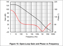
Could you draw that please? I've provided a blank drawing canvas as Figure 1.
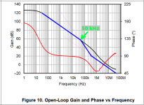
When I try to draw it (see Fig 2) and I select "well outside of the audio bandwidth" to be 50 kHz, the result -- plotted in blue -- doesn't look significantly different from the original. What am I doing wrong?
The -20dB/decade and -40dB/decade slope reminder lines are shown as faint pink
_
Attachments
There is a complete description of this approach here: http://www.ti.com/lit/an/slyt630/slyt630.pdf
It requires an RC between the inputs (not just a C, as that will almost guarantee instability).
Notice the lack of feedback capacitors which would return the noise gain to unity at high frequency, negating any advantage gained by the RC network across the inputs.
It requires an RC between the inputs (not just a C, as that will almost guarantee instability).
Notice the lack of feedback capacitors which would return the noise gain to unity at high frequency, negating any advantage gained by the RC network across the inputs.
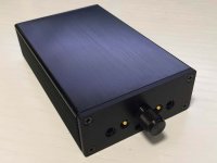
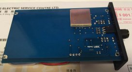
The mechanical parts completed our OPA1622 build.
You can see the thermal flex-pad at the bottom of the PCB directly below the OPA.
This allows a very direct thermal path to the aluminium case extrusion.
Patrick
.
You can see the thermal flex-pad at the bottom of the PCB directly below the OPA.
This allows a very direct thermal path to the aluminium case extrusion.
Patrick
.
Attachments
Opa1622 Dac-out filter
What kind of output filter do you suggest for OPA1622 opamp and AK4490 DAC.
What voltage do you suggest to supply opa1622... output load will be 15kohm shunt attenuator.- What is the best output isolation resistor value?...or no resistor?
Below are 3 choices for output filter... if anybody has better to suggest i will be very grateful and thanks for your help.
Attachments
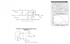
In that application I think a 100 Ohm constant impedance attenuator would be the best. The opamp will drive it nicely, a bridged T with a 100 Ohm load at the destination for the cable will match the cable impedance (if it has any remote importance) and the noise contribution will be very low.
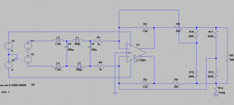
I'm attaching a circuit I have used successfully for Vout dacs that addresses the out of band issues of opamps successfully. The circuit would need revision for a more normal opamp not driving a balanced load.
I'm attaching a circuit I have used successfully for Vout dacs that addresses the out of band issues of opamps successfully. The circuit would need revision for a more normal opamp not driving a balanced load.
Attachments
I just now discovered the OPA1622 reference design at TI.COM. I was impressed by the performance of the design and a question arose in my mind. Is this reference design available for testing?
Edit:
Is this sufficient for a headphone amplifier with a power supply and volume potentiometer:
http://www.ti.com/tool/opa1622evm
The OPA1622 EVM could be paired with PCM2707 EVM to make a less than 200 dollar ultra high quality headphone amplifier + dac combo.
Edit:
Is this sufficient for a headphone amplifier with a power supply and volume potentiometer:
http://www.ti.com/tool/opa1622evm
The OPA1622 EVM could be paired with PCM2707 EVM to make a less than 200 dollar ultra high quality headphone amplifier + dac combo.
Last edited:
Your post made me order one. I will drive it with 2 of these as the board is quite low impedance (1k?). I'll use Meanwell SMPS power.
//
//
I just now discovered the OPA1622 reference design at TI.COM. I was impressed by the performance of the design and a question arose in my mind. Is this reference design available for testing?
Edit:
Is this sufficient for a headphone amplifier with a power supply and volume potentiometer:
OPA1622 Audio Operational Amplifier Evaluation Module - OPA1622EVM - TI Tool Folder
The OPA1622 EVM could be paired with PCM2707 EVM to make a less than 200 dollar ultra high quality headphone amplifier + dac combo.
Any similar OP chips but have lower distortion than this OPA6122?
It depends on the application. We designed the OPA1622 to be able to deliver large current into low impedances with extremely low distortion. For example, I have yet to see another op amp that will deliver 70mArms into a 32 ohm load with the same level of distortion as an OPA1622. Especially when you consider that the OPA1622 only consumes 2.65mA per channel.
If however, you are not delivering lots of current into a low-impedance load, but instead are trying to produce something like 10Vrms into a 600 ohm load, then many more op amps are capable of accomplishing this and may have lower distortion than an OPA1622 if you compared them at high frequency (e.g. 20kHz).
Looking at the EVM schema again as well as the OPA1622 pdf... is the EVM board impedance indeed 61 kohm differential (60k +1k) ?
//
//
Looking at the EVM schema again as well as the OPA1622 pdf... is the EVM board impedance indeed 61 kohm differential (60k +1k) ?
//
Not sure where you get the 60k from? The circuit on the OPA1622 is just a simple difference amplifier made from 1kOhm resistors. For a difference amplifier (assuming a differential input signal), the input impedance on the non-inverting input is 2*R, so in this case 2kOhms. And for the inverting input, where all resistors are equal its R/1.5 so about 667 ohms.
Here is a blog post where I explain this https://e2e.ti.com/blogs_/b/precisionhub/archive/2015/08/14/overlooking-the-obvious-the-input-impedance-of-a-difference-amplifier
You will find one of the best treatments of differential signals and 'ground' is here http://www.hypex.nl/docs/papers/The G Word.pdf from Bruno Putzeys...
It was from the 1622 pdf spec sheet. Page 6 says: Impedance: 60 k diff, 500M C-m.
My reasoning was that 1k in series with 60k -> 61k.
//
My reasoning was that 1k in series with 60k -> 61k.
//
Not sure where you get the 60k from? The circuit on the OPA1622 is just a simple difference amplifier made from 1kOhm resistors. For a difference amplifier (assuming a differential input signal), the input impedance on the non-inverting input is 2*R, so in this case 2kOhms. And for the inverting input, where all resistors are equal its R/1.5 so about 667 ohms.
Here is a blog post where I explain this https://e2e.ti.com/blogs_/b/precisionhub/archive/2015/08/14/overlooking-the-obvious-the-input-impedance-of-a-difference-amplifier
- Home
- Vendor's Bazaar
- New Audio Op Amp - OPA1622