Guys, would you be so kindly and share your OPA1622 Eagle lib with me?
I don't happen to run Eagle, instead I use KiCAD. Here is the footprint for OPA1622 in KiCAD build (2012-01-19 BZR 3256).
Exported footprint with file extension .emp is enclosed within a .zip archive.
Attachments
And build the chassis from plastic (transparent preferably due to physical properties) and you will hear proper, sat free, sound. Most boxes, other mechanics and connectors kill music, ambience and proper height.
//
This misconception must be derived from the fact that many people upon expiration are put in boxes.
However, let me assure you that, except in extremely rare and sometimes criminal cases, the box itself is not the cause of the demise, but is merely a post hoc artifact.
Same so for music, ambience and proper height. It will not be killed by boxes.
Well I did some experiment and this is my conclusion which I now follow when I build anything. It was not a tale from my local undertaker 🙂 Different material effect the field around conductors. So not assured. But I realize this is somewhat challenging.
//
//
Guys, would you be so kindly and share your OPA1622 Eagle lib with me?
I have uploaded my OPA1622 Eagle library to github:
https://github.com/normundss/eagle_libs
Do you mind enlighten the rest of us what different "physical properties" the colored plastic versus the clear one has ???OK. My suggestion was to compare metallic and plastic bolts. And build the chassis from plastic (transparent preferably due to physical properties) and you will hear proper, sat free, sound. Most boxes, other mechanics and connectors kill music, ambience and proper height.
//
Will any kind of plastic box do as long as it's non-pigmented ???
Have you made listening/measurement tests when the PCB is spaced differently from the plastic box itself ???
Your recommendition for minimum distance between PCB / box ???
OPA1622 as DAC I/V conversion
The OPA1622 has been put into service as a I/V for a ESS DAC (ES9018) configured into mono mode with all 8 outputs in parallel. In this configuration the output impedance is only 98 ohm and the current the I/V must source is 31mA P-P. Most opamps cannot source this much current without the THD increasing too much.
In my initial tests the gain is -1.1 for a voltage output of about 3.3V P-P.
The performance of the OPA1622 is not as good when used in inverting mode as it is in non-inverting mode, but the results is still better than any combination of opamps and buffers I have tried before. And I get all that for both positive and negativ DAC output in just one small chip. Very nice.

This is THD measured using R&S UPV showing a nice THD of -121dB at 0dBFS with 3.3V P-P on the output while also driving a 300 ohm load. The higher order THD is from the DAC itself. I can see they change with different digital amplitude. I am not sure if the second harmonic is from the DAC or from the I/V but it sits at -122dBV or 0.00008% and that is about the result from the datasheet figure 17 for a inverted configuration driving 128 ohm which is similar to to the load I have.
Thank you John for a very nice and versatile device 🙂
The OPA1622 has been put into service as a I/V for a ESS DAC (ES9018) configured into mono mode with all 8 outputs in parallel. In this configuration the output impedance is only 98 ohm and the current the I/V must source is 31mA P-P. Most opamps cannot source this much current without the THD increasing too much.
In my initial tests the gain is -1.1 for a voltage output of about 3.3V P-P.
The performance of the OPA1622 is not as good when used in inverting mode as it is in non-inverting mode, but the results is still better than any combination of opamps and buffers I have tried before. And I get all that for both positive and negativ DAC output in just one small chip. Very nice.
This is THD measured using R&S UPV showing a nice THD of -121dB at 0dBFS with 3.3V P-P on the output while also driving a 300 ohm load. The higher order THD is from the DAC itself. I can see they change with different digital amplitude. I am not sure if the second harmonic is from the DAC or from the I/V but it sits at -122dBV or 0.00008% and that is about the result from the datasheet figure 17 for a inverted configuration driving 128 ohm which is similar to to the load I have.
Thank you John for a very nice and versatile device 🙂
> Need a proper build to give it a fair chance.....
http://www.diyaudio.com/forums/vendors-bazaar/283672-new-audio-op-amp-opa1622-5.html#post4729914
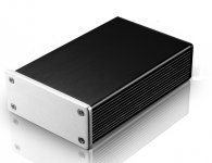
Still waiting for proper machining of the aluminium extrusion case (66x27x100mm), but this is at least a working prototype.
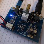
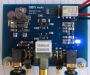
On the right hand size of the last photo is power relay, XEN modified passive Danyuk cross feed filter including volume pot (Vishay P9 conductive plastic).
In the middle above the pot is a JFET follower buffer between the cross feed and the OPA, using 2 pair of matched 2SK209GR.
On the left the OPA1622 cluster as we posted before, and a selection switch for biasing the OPA output into Class A using 2x E103 CRDs.
http://www.diyaudio.com/forums/vendors-bazaar/283672-new-audio-op-amp-opa1622-5.html#post4728662
Works first time.
Patrick
.
http://www.diyaudio.com/forums/vendors-bazaar/283672-new-audio-op-amp-opa1622-5.html#post4729914
Still waiting for proper machining of the aluminium extrusion case (66x27x100mm), but this is at least a working prototype.
On the right hand size of the last photo is power relay, XEN modified passive Danyuk cross feed filter including volume pot (Vishay P9 conductive plastic).
In the middle above the pot is a JFET follower buffer between the cross feed and the OPA, using 2 pair of matched 2SK209GR.
On the left the OPA1622 cluster as we posted before, and a selection switch for biasing the OPA output into Class A using 2x E103 CRDs.
http://www.diyaudio.com/forums/vendors-bazaar/283672-new-audio-op-amp-opa1622-5.html#post4728662
Works first time.
Patrick
.
Attachments
A clear plastic enclosure? I thought that there were a few semi-conductors that were light sensitive. The measures were needed to keep them in the dark.
A clear plastic enclosure? I thought that there were a few semi-conductors that were light sensitive. The measures were needed to keep them in the dark.
This is usually only an issue for ICs in wafer chip scale packages where the die may be exposed to light, but for typical packages the molding compound prevents light from hitting the die. LEDs are a notable exception though and do work as photodiodes.
I do see two glass-encased (what I presume are) diodes. I recall light giving me some excess reverse-bias current in something like a glass-enclosed 1N914 a few years (decades?) back. Moving my hand over the circuit magically changed what it was doing.This is usually only an issue for ICs in wafer chip scale packages where the die may be exposed to light, but for typical packages the molding compound prevents light from hitting the die. LEDs are a notable exception though and do work as photodiodes.
On other things, I recall a few years ago when this audio design was talked about a few years back, the "5532 OpAmplifier" by Douglas Self, with many 5532 op-amps in parallel to get sufficient drive for a loudspeaker (partial magazine article description):
https://www.elektormagazine.com/magazine/elektor-201010/19460
Apparently a large part of the choice for the 5532 was the low cost (there have surely been quite a few made over the decades), making the project practical. The OPA1622 is quite a bit more expensive, of course for several good reasons, but I'm thinking it has higher drive so fewer devices would be needed to make an equivalent amplifier.
Double-checking prices, I just looked on Digikey and noticed they have the OPA1622 listed (in the "Type" column) as Class D! I presume TI would want this corrected:
http://www.digikey.com/product-search/en?keywords=OPA1622
This is usually only an issue for ICs in wafer chip scale packages where the die may be exposed to light, but for typical packages the molding compound prevents light from hitting the die. LEDs are a notable exception though and do work as photodiodes.
Reciprocity is very low, though. Not something I'd worry about.
Do you mind enlighten the rest of us what different "physical properties" the colored plastic versus the clear one has ???
Will any kind of plastic box do as long as it's non-pigmented ???
Have you made listening/measurement tests when the PCB is spaced differently from the plastic box itself ???
Your recommendition for minimum distance between PCB / box ???
OK, I wont go inte details but I suggest you to do some own experiment. A transparent material has some material structure/properties that opaque don't have - it's not immediately about color. This is also quite OT and I apologize that I brought it up and will not comment on it more here.
//
I do see two glass-encased (what I presume are) diodes. I recall light giving me some excess reverse-bias current in something like a glass-enclosed 1N914 a few years (decades?) back. Moving my hand over the circuit magically changed what it was doing.
On other things, I recall a few years ago when this audio design was talked about a few years back, the "5532 OpAmplifier" by Douglas Self, with many 5532 op-amps in parallel to get sufficient drive for a loudspeaker (partial magazine article description):
https://www.elektormagazine.com/magazine/elektor-201010/19460
Apparently a large part of the choice for the 5532 was the low cost (there have surely been quite a few made over the decades), making the project practical. The OPA1622 is quite a bit more expensive, of course for several good reasons, but I'm thinking it has higher drive so fewer devices would be needed to make an equivalent amplifier.
Double-checking prices, I just looked on Digikey and noticed they have the OPA1622 listed (in the "Type" column) as Class D! I presume TI would want this corrected:
Linear - Amplifiers - Audio | Integrated Circuits (ICs) | DigiKey
Glass encapsulated diodes are another example for sure, can't believe I forgot that one!
If you make a massively parallel OPA1622 amplifier please post pics! A fellow TI employee had mentioned doing a project like that a few months ago but I'm not sure how he progressed. He's based in Dallas (not Tucson, AZ where I am) so I don't see him often enough for project updates.
And thank you for pointing out the "creative" categorization of the OPA1622. I can ask our marketing team if this is something we can point out to the distributor.
Reciprocity is very low, though. Not something I'd worry about.
Agreed. Although UV LEDs make great little detectors! They're cheap and are only sensitive to photons at or above their bandgap energy (typically wavelengths shorter than 400nm-ish). But this off topic 😉
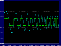
We tested the amp with multiple headphones and found that it has instability (?) with one.
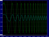
The first picture shows the normal output of left (cyan) and right (green) channels using a MAX471 as load.
The sweep sine was fed to the right channel with the left channel grounded BEFORE the crossfeed.
So the left channel input signal to the OPA is a result of the cross feed buffer.
The second picture shows the same with a Fostex TH900.
The amp seemed to shut itself down ??
We checked that the input signal is normal.
Adding a Zobel did nothing.
Adding a 10R resistor between OPA out and phone returned the output to normal.
We had no such issue with the TH900 with other headohone amps.
Comments most welcome.
Patrick
.
Attachments
The OPA1622 will shut itself down if the die temperature gets too hot. What power supply voltages were you using and is the thermal pad tied to a decent amount of copper? I'm skeptical that this is a control loop instability (although it's not impossible), but rather a thermal issue.
Hi John,
Thanks for the feedback, I'm the tester of the amp that Patrick refers so maybe I can provide more info. The power supply voltage is 9V, and the thermal pad is tied to a decent amount of copper (which is further thermally connected to more copper by a 3M thermal pad).
When the issue occurred, the case temperature of the OPA1622 was around 34 degC (measured by a DMM temperature probe touching the case for a few minutes). I have also done some stress tests earlier, with a 30R resistor as load and rather high current output, the OPA1622 case temperature went up to 63degC and yet it was working properly at such higher temperature.
I have made 2 test units and the same issue occurred in both units, however, among the 10 headphones I've tried, the issue only occur with a re-cabled Fostex TH-900 headphone.
Thanks and regards.
Hmm. I guess this may be a stability issue then. Although the only way the OPA1622 would shut down is if the die temperature exceeded the thermal shutdown trip point. Remember this is die temperature not case temperature. And die temperature can change extremely fast due to the low mass and relatively high thermal conductivity of the die. It's possible that the re-cabling of the Fostex headphones created a very large capacitive load for the OPA1622 which is causing it to be unstable, and high frequency oscillation is causing excess power dissipation in the die. I guess there's also a possibility that there is a short in the headphones, but I believe you stated that these headphones were used to test other amplifiers without any issue, correct?
I agree it is a stability issue with the capacitance of that particular headphone.
This is supported by the fact that a 10R in series returns it to stability.
We also have marginally stable amplifiers exhibiting similar behaviour (unstable with some cables).
But we also have discrete amps that can cope with such cable capacitance.
As a commercial product from TI, especially with the wide range of compatible phone impedances as promoted here,
perhaps you might wish to look at this more closely yourself.
For us, it was a fun project, and we now know its limitations.
Best regards,
Patrick
Last edited:
- Home
- Vendor's Bazaar
- New Audio Op Amp - OPA1622