Really what I want to do is have the protection circuitry do nothing until it's absolutely necessary.
If I put the standard VI limiter in this circuit monitoring the power BJT emitter resistors it starts clamping way before it’s required. I don’t mean it pinches it off completely, but my distortion figures start rising dramatically. So I was hoping for a diff. way to monitor it. I realize I’m still measuring a resistor drop based on the current, but it doesn’t distort like the standard limiter does.
If I put the standard VI limiter in this circuit monitoring the power BJT emitter resistors it starts clamping way before it’s required. I don’t mean it pinches it off completely, but my distortion figures start rising dramatically. So I was hoping for a diff. way to monitor it. I realize I’m still measuring a resistor drop based on the current, but it doesn’t distort like the standard limiter does.
most close protection approach in a commercial device I know is those from Linn's Klout - check out the schematics from my postings #51+52 underI am trying to figure out a new way to protect my amplifiers. The old VI limiting always adds non linearities to the signal as it approaches the limit, or even much earlier in some cases, which is very undesirable in my mind, or ears. While I’m sure someone else has already tried this, Id really like to figure this out.
My solution works great at removing the non-linearities and still protects the amplifier (sort of) but the trip point is kind of slow (1 or 2 ms) and the current reaches 60 amps before the protection cuts off the signal. Mind you the test I did is all on Multisim not real world, but I’m building it now.
What I’d like to know is if this is a dead-end path? I just need to figure out some way to cut off the signal earlier, or I could double up the output devices. IDK any suggestions would be awesome.
https://www.diyaudio.com/community/threads/tweaking-classic-linn-lk1-lk2-lk280.106226/page-3
You can monitor the voltage across the emitter resistors and trigger your latch when the current gets too high. A voltage divider between the emitter resistors and the thing that detects whether the voltage is too high (Q16) allows you to select whatever threshold you consider necessary.

My first impression was that the circuit in #1 was the protection circuit without the amplifier. There are better ways in drawing a circuit or is the drawing surface limited to letter size? Colours for functional block would improve things very much. Supply rails are at top and bottom, but not indicated as such. As if they exist, but having nothing to do with the amp and the protection. Most commercial enterprises use a 10 cent fuse on the rails instead.
edit: did some scrubbings
edit: did some scrubbings
Attachments
Last edited:
Something that might be worth considering is the use of a closed loop hall effect current transducer. It could be in either supply rail, and the outputs are electrically isolated from the current being measured. The have excellent bandwidth, linearity, and step response; they are commonly used to protect and monitor inverter drives, with pwm waveforms of 20 to 50 KHZ. They are a little pricey, in the range of $20 or so. They might also offer some possibilities of intelligent bias control. I have used them in high performance monitoring and feedback systems and they do perform as advertised.
Interesting thought about the Hall Effect devices, I am playing with some of these for a completely unrelated project, battery management on a boat.
Rather less than $20, more like $5
https://www.ebay.co.uk/itm/124474351599
Apologies to the OP if I sound a bit caustic about his ideas, we should be open to dsicussing stuff and appreciate people who throw ideas into the ring, it might make us think!
Rather less than $20, more like $5
https://www.ebay.co.uk/itm/124474351599
Apologies to the OP if I sound a bit caustic about his ideas, we should be open to dsicussing stuff and appreciate people who throw ideas into the ring, it might make us think!
How 'new' is this approach really?
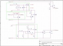
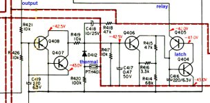
Cleaned up & boiled it down to the essence.
Amazing how much the dc detectors resemble a bit older design.
And detecting the base current of the PNP output device, up to 6mA is allowed - do forget the top half.
Once reached, the protection trips into utter freeze until powered off.
I do have an opinion about this design.
Thought of this one too.
Hall sensors. Never thought of them, but not strange.
Philips used them in their Motional Feedback loudspekers (80's), not a great succes though.
What is the frequency response?
Attachments
Off topic: when you think you have come up with something new, there is always a chance that someone else came up with it earlier. For example, I recently learned via this forum that a distortion compensation technique I thought I had invented in the 1990's has been used in valve amplifiers since 1954. The implementation details were different, but the basic idea was not. I had a similar thing with a special crystal oscillator once, but that had only been known for a decade or two when I "invented" it.
Reinventing the wheel is not a shame, but retracing the trodded - lost - path again.
Some folks prefer to stumble over the cobble stones, breaking legs and necks, hastely out of breath, to mark their existence.
So much for the off topics. No justice, just acceptance.
Some folks prefer to stumble over the cobble stones, breaking legs and necks, hastely out of breath, to mark their existence.
So much for the off topics. No justice, just acceptance.
The problem with conventional output protection is that it leaves the protection fighting the VAS and IPS, which is one reason they are often unstable. I like the idea of conventional VI limit detection that drives an input (AC) attenuator, probably a JFET shunt. This leaves the feedback control intact and hopefully stable. Another approach is just using enough silicon in the output to blow a fuse first, ~BGW.
PS: and conventional protection changes the output impedance, causing a flyback reaction.
PS: and conventional protection changes the output impedance, causing a flyback reaction.
Last edited:
I've sent the files off to Jlcpcb with extra test points to get some real world data. Multisim tells me this circuit is good and works as expected but i'm still concerned about the few 10 of ms before the differential cut out kicks in and the output current rises to high. I'm not sure who said it but c12 and c13 were added after I found the square wave response at 100khz sent the amp into oscillation and these fixed it without affecting the top end roll off and thats all they do, or at least that is what multisim thinks, we'll see.
I also noticed a few others pointed out this had allready been done but nothing posted that I saw was monitoring something that doesn't affect the audio yet reflects output current and when active cuts out the diiferential stages completely removing the current the following stages.
I agree that adding some form of output transistor temp moniotring to adjust the trip point (soa) would be useful, but I'm not copying, I'm trying to figure this out on my own.
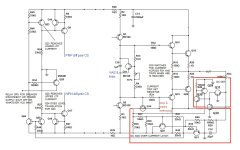
Oh and how does anyone who knows how amplifiers work think what I originally posted was just the protection mechanism? + rails always ontop - rails always on bottom. Theres a clear diferential stage, vas stage, output stage, I'm confused how you don't know what an amplifier looks like
Who says we don't?
You posted a transistor salad where 15 transistors are the actual amplifier, 16 the newfangled protection circuit.
Since they are all intricately interconnected, direct coupling all over the place, we analyze it as a whole.
Again, monitoring current through ballast resistors and nothing else is the straightforward solution, and can't be accused of VI protection sins because of is not VI but I sensitive only.
Yours is also I sensitive only, only using an indirect detection method which depends on individual transistor parameters.
That's why I suggested adding trimmers for proper adjustment.
"What" does the circuit do after it detected over current is something else: relay opening speaker out or power rails, FET or LDR shunting input, nuking input stage, triggering a crowbar across speaker out or supply, there's many possible paths.
In fact, a VI overload detector might do the same.
Clamping driver drive current, what you (and many) don't like is not the only option, by far.
FWIW in my large Bass amps, also in powered mixers, I often use a VI triggered SCR, go figure, which drives a relay disconnecting speakers.
Being quite the minimalistic guy, my full VI protection uses 5 components total, plus a relay.
SCR latches it OFF until power is turned OFF by user when it self resets.
@Easyamp - This amplifier works only in simulation. See this thread for an explanation. https://www.diyaudio.com/community/...nce-hyrid-mosfet-audio-power-amplifier.404839
Ed
Ed
I disagree and we'll soon see. oh by the way this is why I left diyaudio 10 years ago and never potested. the responses were uselss. carry on my friends
Maybe you would get more desirable responses if you answered two basic questions:
1. Why do you believe that sensing a base current and triggering a latch when it is too high has less effect on sound quality than sensing the sum of the emitter currents and triggering a latch when it is too high?
2. When you look at the waveforms in your simulation, can you identify in what part of the circuit most of the delay is located?
What happens when the protection kicks in? The current sources switch off, the differential pairs switch off, the current mirrors switch off. That leaves the bases of Q1 and Q2 floating atop C12 and C13. And what then? Will it take some time (delay?) before the charge of these caps changes due to the base currents?I'm not sure who said it but c12 and c13 were added after I found the square wave response at 100khz sent the amp into oscillation and these fixed it without affecting the top end roll off and thats all they do, or at least that is what multisim thinks
Did you simulate the working of this protection circuit? Did you simulate the behaviour of the protection circuit when the amp is powered on and powered off?
REALLY? ....... In DIY Audio?I'm confused how you don't know what an amplifier looks like
So far I only found honest answers to your questions.oh by the way this is why I left diyaudio 10 years ago and never potested. the responses were uselss. carry on my friends
That.1. Why do you believe that sensing a base current and triggering a latch when it is too high has less effect on sound quality than sensing the sum of the emitter currents and triggering a latch when it is too high?
Fwiw here is my latching, fast, non signal distorting minimalistic protector.
I still use quasi-complementary power stages, so all NPN or NCH MosFets, same thing.
Transistor shown is one on negative rail.
Re is the existing ballast resistor.
Detector/latch is a 50 cent TO92 SCR, MCR100, any letter will do.
Its gate is prebiased by R2 to about 0.35V but that drops when output swings downward IF a proper impedance load is present.
The current sampling section (Re R1 R2) allows 8-10A (my choice) into the load so no clipping, blocking, instability, anything.
With a shorted output, trigger current is half maximum, so 4-5A (thanks to prebiasing)
In that case, SCR triggers (instantly) and latches, disconnecting load.
R4 allows 24V relay coil to match available rail voltage.
Protection stays latched until amp is turned OFF and main capacitors discharge.
If amp is turned On again without solving the short problem (typical of impatient Musicians) , amp self latches OFF again, even on turn on thump.
Yes, I only monitor negative rail transistors; Music is AC anyway so I am only "wasting" one half cycle, at any frequency which is going through.
In case somebody misses it, it IS a VI protection, sensitive both to current and voltage across power transistor.
Whitebeards will recognize the prebiased trigger network, popular in the early 70s, notably used in Acoustic amplifiers, of The Doors, Led Zeppelin and Jaco Pastorius fame, but also on some British and Australian HiFi amps.
There, of course, they just clamped driver transistor current and might cause flyback pulses with very reactive loads, not the case here where the action is more drastic: either "do nothing" or OFF.
Almost forgot: for peace of mind, you can add a small capacitor (say .1uF ceramic) across R3 to prevent high frequency noise triggering, although I never experienced that.
Music waveforms are not symmetric by any means though. Lots of 2nd harmonic out there....Yes, I only monitor negative rail transistors; Music is AC anyway so I am only "wasting" one half cycle, at any frequency which is going through.
True enough.
That said, into a short, current goes through the roof, on both waveform halves, even if highly unsymmetrical.
Say unshorted positive signal is 30 Volts peak, negative is 4 Volts peak?
Think "dividing by zero" : any negative voltage Amplifier tries to put out will trigger this.
Not impossible to cheat this protection: it only takes to send a steady stream of positive peaks only, into a DC coupled amp, or short it with a BIG diode, cathode to ground.
So far it hasn't happened 🙂
- Home
- Amplifiers
- Solid State
- New approach to amplifier protection