Good evening
I am planning e new tube amp project, with E83F and the 807 (5B/250M)
Thought I`d run the E83F at B+ 300V, bias 3,5V, Iq 12,5 mA, RL 15k, and Vg2 at 150V
807 will be at B+ 480V. bias -25V, Iq 50mA, Vg2 at 300V and an 10k load.
Will use the PSU from my former build just to check the circuit, OPT will be Hammond 125ESE. It`s cheap and can be hooked up for various impedances.
Biggest issue will probably be keeping steady Vg2. For the E83F a voltage divider would probably do the trick, it will keep the voltage within a few volts, but the 807 might need VR tubes to avoid burning to much power through a voltage divider.
These tubes are still cheap and it is interesting to dive deeper into Vg2 issues in the circuit.
Any thoughts on the matter?
Go ahead and use a series resistor and two OD3 tubes in series for the 807 screen.
Then use a different Resistive divider and bypass cap for the E83F B+.
That way any small variation of the 807 screen voltage will not get into the E83F supply.
Since the E83F is operated as a pentode, any variation of the plate voltage as the mains voltage goes up and down, will not matter.
You might use a series resistor and a third OD3 to run the E83F screen.
Wow, what a pretty amp that would be!
Yes, that was indeed the idea🙂
I`d most of all like to supply both grids from one VR pair, E83F g2 supplied from between the tubes, but I am not sure there is enough mA`s when both grids pull away. 0A2 are marginal, 0D3`s might be enough.
E83F grids won`t load down the VR`s but they might be the drop... These are easy to get within 2-3V anyway with a voltage divider.
VR tubes are cheap anyway, I will buy what I need to test.
I am working on the circuit but I do not have it ready yet.
Dynamic impedance of VR tubes:
Two 0A2 in series: 160 Ohms
Two 0D3 in sereies: 229 Ohms
That is a lot lower impedance than any 'medium power dissipating' resistive divider.
A bypass capacitor will lower the impedance, but the DC voltage will not be constant if either the screen load current varies, or if the mains voltage varies.
On the issue of steady g2 voltage.
Can`t I just rectify 230V straight from "the wall"?? That should leave me with ca 320 V before filtering with RCLC. Then I`ve got approx 300VDC directly and 150 through a divider, or a VR tube.
Should be a steady voltage with a low source impedance, and not influenced by varying current demand by the tubes.
Is this a good way to go?
Hi
Would you care to explain?
It will be double fused, both from the amps fuse and one of its own, maybe 0,1A.
Or is there other considerations? The way I explained it will be floating, will that be a problem?
Would you care to explain?
It will be double fused, both from the amps fuse and one of its own, maybe 0,1A.
Or is there other considerations? The way I explained it will be floating, will that be a problem?
There are many different power mains systems in the world. Some are ground referenced back at the panel where it comes into the home. Some are balanced. Some are 'floating'. There are many failure modes of the power mains (power still present, but with ground at what was a 'floating' wire, open neutrals causing 2X voltage, open grounds, etc.). There are many failure modes of amplifiers. You need to use a transformer to power your amplifier. The secondaries need to be used for B+, regulator tubes, filaments, etc. I have worked in areas of the world that had power mains different from what I have in the US. And I have worked with corporate safety groups, and with groups like UL. Safety First! Failing to use proper designs, and safe practices can result in the following: "The Surviving Spouse Syndrome". A 0.1 Amp fuse will not protect a user who comes in contact with a power main circuit, inside or outside an amplifier.
The big risk is that you (or someone else not knowing your "clever" idea) turn over the mains plug, so that the line would go to the chassis (or signal GND) and neutral to the rectifier diodes that produce B+. It can kill you.
You need to use a transformer anyway, you need to give the tubes 6.3V for heating. And a negative bias.
BTW, I use the 807 from 425V (anode and g2) without any issue. But I will modify the power supply for 300V just to be on the safe side.
You need to use a transformer anyway, you need to give the tubes 6.3V for heating. And a negative bias.
BTW, I use the 807 from 425V (anode and g2) without any issue. But I will modify the power supply for 300V just to be on the safe side.
Hmm ok, maybe not a good idea then...
But just to clarify, we do not have "live" and "neutral" over here where I live, we have two live wires with approx 132V (live)wire-ground, and 230V wire-wire. Hence there is no wrong way, works either way.
I am not sure what this power grid distribution is called, might be TN.
The two live ones might be rectified with full wave rectification, with ground as both safety ground and circuit ground. Chassis will be connected to this earth ground .
I am probably missing a point here...
Edit:
I will use a transformer for the amp, the idea was to supply a stiff Vg2 supply that was independent from the rest of the circuit.
Last edited:
In the beginning, 807s were rated for 300V screens, 600V plate. They were designed to be used in RF transmitters. They drove Pi filters to very high voltages (up to 2X B+) The control grid had a large signal, went to zero volts, and then beyond to perhaps +10 or +20V. There was lots of control grid current. At that point, the plate would swing downward from 600V to perhaps as low as 50V. But with the control grid positive, and the screen still at 300V, the screen was drawing very large currents.
Later applications of the 807, like Triode Wired Mode, the screen and plate were tied together (usually with 100 Ohms from screen to plate). In that case, the screen rating was 400V. Now, the plate would swing downward from 400V to perhaps 50V, but the screen was also at 50V, so there were no large screen currents.
The key to screen current is how much lower the plate voltage is than the screen voltage.
Ultra Linear is another mode. The screen voltage starts just a little higher (perhaps 10V higher) than the plate voltage, due to the DCRs of the output transformer primary. A 40% UL tap, means that when the plate swings downward from 400V to 50V, the screen swings from 410V to 270V. In that case, there is a medium large screen current.
Look at it this way, 132V line to ground gets 187V peak to ground after you rectify it. But your screen needs 300V to ground.
Also, you need a dropping resistor to drive the OD3 (the OD3 does not ignite at 150V). OD3 160V ignition, OD3A 180V ignition. 185V B+ and a series resistor to the OD3 is required. 5 to 40mA regulation is the range. Once a regulator tube ignites, it stays at its voltage. Without a series resistor, it will blowup if the voltage is more than the regulator operating voltage. If the screen current is 5mA, and the OD3 current is 20mA, the total current is 25mA. 185V - 150V = 35V 35V/0.025A = 1400 Ohms (one tube 150V regulated). 185V x 2 = 370V 370V - 300V = 70V 70V/0.025A = 2800 Ohms (two tube 300V regulated). Now, if the screen draws 20ma during max signal, there is still 5mA to keep the OD3 ignited. A lot to consider when using a simple regulator.
Hmm, I am pretty sure it will be 230V X 1,4= 322V rectified, then some loss in filtering.
Over here the ground wire is for safety ground or earth ground, it is not one of the two pins in the socket, and therefore not necessarily part of the circuit.
For example a light bulb is connected between the two live wires, resulting in 230V. If the socket has earth, not every type has it, it is connected to the chassis/structure.
I do not mean to come of as a smarta** or anything but I suspect I cannot explain good enough what I mean.
On the other hand, thanks for input on 807/VR tubes.
Edit:
I might be tired or sth... In my amp I got appr 480V raw DC from a 360-0-360 transformer with full wave rectification. What will a rectifier bridge with 230V be then? Shouldn`t it be 320V?
Last edited:
Viking 83,
I believe you said one mains line is 130V from ground, and the other mains line phase (opposite phase) is 130V from ground.
Do not consider the numbers below to be exact, just look at how things are connected, and the consequences . . .
If you use mains of 230V differentially, you have to use a bridge rectifier (full wave rectification). Or you use a diode on one phase of mains of 130V to ground, and a diode on the other phase of 130V to ground. Then you have a minus 1.4 x 130V, -182V (below ground), and a plus 1.4 x 130V, +182V (above ground).
In either of these cases, this will be the result: You will have one end of the VR supply (-182V, below ground), and the other end of the VR supply (+182V above ground).
Which of these voltages will you tie to the star ground, and chassis ground, and input connector shield (ground), and output transformer secondary Common? in either case, the amp grounds will be 182V away from ground.
There are no 'floating' power supplies in this case.
Now you find the shocking truth. Transformers save the day.
Last edited:
Ok, I guess this was a dead end... Thanks guys, you may have saved me from an expensive and possibly dangerous mistake.
How many volts (or percentage) is considered good enough?
One datasheet stated within 5 %, that`s 15V on the 807 g2.. Sounds like a bit much.
How many volts (or percentage) is considered good enough?
One datasheet stated within 5 %, that`s 15V on the 807 g2.. Sounds like a bit much.
The OD3 150V will change by 4V when the current in the tube changes from 5mA to 40mA. That is 2.7%. Two OD3 in series: 300V will change by 8V when the current in the tube changes from 5mA to 40mA. That is also 2.7%. One OD3A will change by 5V under the same conditions. Don't worry too much about a 2.7% change of the 300V screen.
If you know the actual screen current, you probably can adjust the series resistor from B+ to the top of the OD3 series string. For example, if the actual screen current is no more than 5 mA quiescent, then you could make the total current of the screen plus the OD3 current to 15mA, instead of the 25mA I recommended). That will allow the screen to draw up to 25 more current during maximum signal.
There are many other factors to create a good, reliable, and good sounding amp. And there are always other voltages in the amp: My power mains vary from 117V to 123V. That is a 5% change. Most of my power transformers filament secondaries put out about 6.8V. I use a dropping resistor, so that at 120V, the filaments receive dead-on 6.3V. That also provides an intrinsic soft start on the filaments. Nice.
I design the B+ and the cathode self bias to be what I want when the power mains voltage is at 120V (the center of the mains variations).
Do not design an amp to stress all the factors of a tube to be at all the limits at the same time. Maximum of the: plate voltage, screen voltage, cathode current, filament voltage, plate dissipation, screen dissipation, etc. You get the idea. If you need to push a tube harder, you either need parallel tubes (another story), or a different tube.
Last edited:
I anticipate a current draw of 5mA pr 807, 2-8 mA at min max and 2,6mA pr E83F 1,6 - 3,6 min max.
Am I way of or do these values seem ok?
Calculated on basis of the relation between Ia and Ig2 at somewhat similar operating conditions/voltages in the datasheet.
Am I way of or do these values seem ok?
Calculated on basis of the relation between Ia and Ig2 at somewhat similar operating conditions/voltages in the datasheet.
Sometimes you have to adjust a circuit according to the tube, Mains voltage, B+ drop, etc.
If you use a 100 Ohm resistor to each 807 screen, you can read the voltage drop, and calculate its quiescent current. And you can read the voltage across the E83F's plate resistor, and calculate its quiescent plate current.
If you start with currents that are a little on the low side, you can adjust for more. Starting with way too much, you have to measure quickly and turn it off.
There are lots of circuits that show voltages and currents around an 807.
Be sure to use a proper bleeder resistor across the B+. Then (carefully) read how quickly (or slowly) it goes down to a safe voltage when the amp is turned off. It takes longer if the tubes are out; but some amp topologies do not drain the B+ much faster than that even if the tubes are in place.
Calculate your open circuit B+, to be sure if a tube does not turn on, etc., that the capacitors voltage rating is not exceeded.
You could start with a proven circuit, and then later re-design, or design your own after that. Many schematics on the web are not actually tried and proven; or are not reliable for the long haul.
Generalization, an SE amp with out any negative feedback: Using the 807 in Pentode mode will give the most power, and the most distortion, and lowest damping factor. Using the 807 in Triode wired mode will give the least power, and the lowest distortion, and highest damping factor. Using the 807 in Ultra Linear mode will give medium power, medium distortion, and medium damping factor (relative to the other two configurations). But the 125ESE will not allow for Ultra Linear.
You can try Triode wired mode, as long as the screen voltage is not more than 400V. Connect the Screen to a 100 Ohm resistor, and the other end of that resistor to the plate.
With the 480V B+ you planned on using for the plate, you need to stay in Pentode mode, and stay at 300V or less for the screen.
Hi guys.
I have finished the amp now, plays quite well if I may say so myself. Bought the Hammond 372 HX for power, but I should probably have gotten the 373 HX. With the 372 I had to go with diode bridge an LC filtering, got a rather high voltage and the first L in the filter hums like crazy. With the 373 I could use full wave rectifier an CL filter, that worked perfect during mockup so Ill go back to that.
I am using VR tubes for 807 G2, and potential divider for E83F G2. Tried tapping E83F G2 voltage between the two VR tubes but that was no succes whatsoever. Started crackling after 10-15 seconds, so I soldered the divider back in.
Attachments
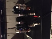
Viking83,
Your amp looks great!
I am glad you are enjoying listening to it.
It would be nice if you could post a schematic sometime.
Your amp looks great!
I am glad you are enjoying listening to it.
It would be nice if you could post a schematic sometime.
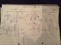
I only have one of the sketches here at work, I can post it but be warned🙂 I have a few tweaks to the circuit so it is not 100 % accurate.
I have ordered another mains transf than the one I have on now. Full wave rect. resulted in to low B+, and rect. bridge a bit too high.
Tried to make it work with LCLC filters, but the hum from the first PSU choke is way to loud...
A 700V CT tranny will be spot on.
Also I went with VR tubes for 807 g2, dead steady voltage at 297V. Maybe I will try to supply the E83F g2 to from between the tubes, but I am not sure I can load the VRs with more mA..
Attachments
- Home
- Amplifiers
- Tubes / Valves
- New amp-project; E83F / 807