Good evening
I am planning e new tube amp project, with E83F and the 807 (5B/250M)
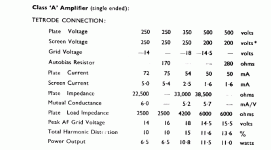
Thought I`d run the E83F at B+ 300V, bias 3,5V, Iq 12,5 mA, RL 15k, and Vg2 at 150V
807 will be at B+ 480V. bias -25V, Iq 50mA, Vg2 at 300V and an 10k load.
Will use the PSU from my former build just to check the circuit, OPT will be Hammond 125ESE. It`s cheap and can be hooked up for various impedances.
Biggest issue will probably be keeping steady Vg2. For the E83F a voltage divider would probably do the trick, it will keep the voltage within a few volts, but the 807 might need VR tubes to avoid burning to much power through a voltage divider.
These tubes are still cheap and it is interesting to dive deeper into Vg2 issues in the circuit.
Any thoughts on the matter?
From the STC 807 report (attached) the THD is quite high, as is the case for all SE pentode amps. Making the plate load lighter than specced will improve harmonic performance somewhat at the expense of output. The 807 will require gNFB to clean up the mess, and to provide for speaker damping, which pents don't do well due to the high rp. The 807 also likes to make high order harmonics and open loop sound very harsh. Screen voltage regulation will definitely improve the performance. VR tubes are good, but an active screen voltage regulator will be better still. You avoid having to run so much current through the VR tubes, and keeping the current down improves regulation, and reduces the heating.
The screen voltage for small signal pents can come from a voltage divider, a Zener, or those neon panel lamps like an NE-2. ) If using neon lamps or any other gas discharge device, don't try bypassing them with a parallel capacitor as the resulting negative resistance characteristic will make an oscillator.)
On the issue of steady g2 voltage.
Can`t I just rectify 230V straight from "the wall"?? That should leave me with ca 320 V before filtering with RCLC. Then I`ve got approx 300VDC directly and 150 through a divider, or a VR tube.
Should be a steady voltage with a low source impedance, and not influenced by varying current demand by the tubes.
Is this a good way to go?
Yes, of course you can, but "Can I?" and "Should I?" are two different questions. Yeah, back in "the day" there were just ESSSSSSS-loads of "straight from the wall" designs for TV sets (why you see so many types with goof ball heater voltages) those "AA-5" radios, and audio amps (the 1st, 2nd, 3rd, 4th Boys' Books of Electronics were lousy with them). It wasn't a good idea back then, and it's not a good idea today. Considering the possible equipment destruction, the trips to the emergency room if you're lucky -- or the morgue if you're not -- saving the cost of a PTX is a false economy. Don't do that, just don't.
Attachments
Hi
On the last section of your reply, I`ve read up on isolation transformers since, and finally got the point. Did not quite understand the problem earlier, numerous sources states you should use isolation transformers but very few explain why exactly, in a way I can comprehend anyway...
Needless to say, I`ve wired the amp as it should be🙂
Used anode-anode feedback (Schade?) but I might experiment further with gNFB. I like the sound of it as is, but it should be a quick experiment so why not.
Also considering Voltmeters an a Ammeter on the front, Bias for input and output tubes, and B+/807 Vg2. Toggle switches 1-0-1 for bias check on each E83F, each 807 and B+/Vg2. I suppose it is more of a design aspect vs technical significance but I thought it might be cool.
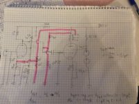
1. For the Schade feedback, you do not need the feedback resistor that goes to ground.
The rp of the input tube, in parallel with the RL of the input tube is all the feedback divider you need (Rf resistor and Cf capacitor drives the parallel impedance of input tube rp and RL).
The capacitor Cf will cause a rise of gain at low frequencies (less negative feedback as the capacitive reactance of Cf increases at low frequencies).
Some Schade circuits use that cap, but many do not. If there is no capacitor, then the feedback resistor Rf becomes an additional source of current to the input tube plate.
Some readjustment of the plate load, RL, may be needed.
You may want to raise the impedance of the input tube rp, you can do that by taking out the input tube bypass capacitor; but that will reduce the gain, even before you apply the schade feedback.
You can do a partial increase of the input tube rp, by splitting the 1k cathode resistor, and putting the bypass cap across only the top resistor. Examples are: 500 Ohm and 500 Ohm in series, or 900 Ohm and 100 Ohm in series. Bypass cap across one 500 Ohms gives less gain than Bypass cap across 900 Ohms.
2. For the global feedback, the input tube cathode bypass cap is shorting out the feedback signal from the feedback resistor.
Instead, take the value of the input bias resistor and divide it.
The input tube bias resistor is 1k. Instead, use a 900 ohm resistor from the input tube cathode in series with a 100 Ohm resistor to ground. Put the cathode bypass capacitor across the 900 Ohm resistor, and connect the feedback resistor, Rf, from the output transformer, to the junction of the 900 Ohm resistor and 100 Ohm resistor.
Have fun trying different circuits and listening.
Last edited: