Has anyone check my A75 in Pass DIY Gallery. That was built in 1995 and is my best work so far. I know I shouldn't be braggin' about it but I just can't help it. Sorry. Maybe it will end up in creative discussion on building amps instead of countless posts on designing PCBs and resistors (capacitors) substitutions. On the other hand don't take me too seriously, because I am aware that this is what this forum is for.
http://passdiy.com/gallery/a75-p7.htm
http://passdiy.com/gallery/a75-p7.htm
Parts Quality
"All the resistors are Holco, wiring by Kimber and Cardas."
Hmmm......I also see some Panasonic HFQ,MIT,and Wima caps and aren't those Edison Price binding post? But good parts aren't that big a deal right?
"Maybe it will end up in creative discussion on building amps instead of countless posts on designing PCBs and resistors (capacitors) substitutions."
And maybe not..........
H.H.
P.S. Very nice job, did you design the PCBs?
Yes I designed the boards because I wanted to achieve the shortest signal path traces and avoid wiring whenever possible. The input jacks and a balance switch are attached directly to the front end board. Also the regulated power supply board is positioned in such a way that wires to input board are very short. I used HFQ caps for main filter caps because by taking advantage of their small size I could position them almost beside output devices. Mounting TO-3 otput devices is quite tricky too. You cannot mount them flat on a heat sink but on some kind of an angle, or if you want to do it nicely, a custom bar. Most of the manufacturers use screws to conduct the current to the devices (unless you don't use the isolation pads). I didn't want to go that way and soldered pieces of wire to the mosfets.
When you notice the way tose amps stand on the floor, behind the speaker it would be awkward to place the binding posts (yes, Edison Price) in the back. That's why I chose to put the binding posts on a front panel. Although yet, I'd like to see an amp company that does it. Those are big monoblocks that stand on the floor and not on the rack and each foot of quality speaker cables is expensive.
Regarding parts quality, remember it was 1995 and for me Holcos were as high as I could go. Vishay and Caddocks products seemed to be ridiculously expensive. I used nice binding posts though (maybe becase they were in the front?)🙂
Also anybody notice the way the transformer is mounted. However this is not my idea. I've seen the picture of Aleph 0 in a German magazine and I liked the way the transformer was mounted there. You can probably see that the amp takes a lot of influence from early Alephs designs although it can stand on it's own ground as well. I must add that I admire Nelson Pass work immensly and take a lot of inspiration from it.
A75
Peter,
How do you go about planning the design of the chassis (obsolutely no discussion of electronics or pcb on this post)? I'm jogging down some points here. Hopefully you can shade some lights on it and gives us some pointers.
- It almost look like every piece of metal is custom made. Are they? Do you sit down and draft it up exactly to the nearest 1/16" and then have a company made it for you?
- They all looks very expensive - every piece of metal. How do you cut cost? I know DIY does not necessary means cheap.
- Where do you get all the mechanical parts?
- How do you cut the metal and drill holes etc ...... to make it all fit so nicely?
- Do you always design the chassis first and then decide on the heatsinks later?
- Do you cut the sheet metal yourself? What are some of the tools you use?
- What is the thought process that gives the shape of the amp?
- Do you aim for more height than width (or depth) of the amp? And why?
- Do you take into consideration of the EMF, etc... when designing the chassis layout?
- Do you overdesign the heatsinks (in terms of heat dissipation) rather than just enough?
- And so on .......
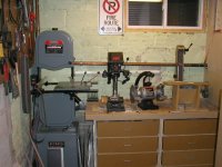
Now we are going somwhere. Maybe Harry wasn't right after all and that discussion would be creative. The picture below shows everything you need to do that kind of work. I have it organized now in a basement but before I was doing everything in a garage.
That's true that every piece of a chassis is custom made, but it's not really hard.
When I started the design of a chassis the heat sinks where the starting point. I can't imagine other way. You build the whole amp around heat sinks. And of course transformer, you have to know how big it's going to be in order to fit it into chassis. I never sit down and draft everything. I just have the vsual idea in my head of an amp and go along. In that case heat sinks determined the height and depth of an amp and transformer determined the width. Nothing to measure. The heat sinks by the way are from R-Theta and I ordered 12 pieces of them. The length I calculated to obtain proper heat dissipation, also didn't want them too short because then the amp would be lower than Aleph0.🙂
Coming back to tools, all you need is a band saw, table drill and belt sander. In 1994 I bought them all for $CAD400. Not all of them were new.
Attachments
Having decided on the dimentions of the amp I check if all the parts (mostely filter caps, because there are many of them and they big) would fit inside amp and I start cutting aluminium. For that project I ordered plates precut to the width from local aluminium manufacturer, I just had to cut them to the length and finish the edges which I did on a belt sander. As you see on a picture I modified my belt sander by installing oversized mdf table so 90 deg. angles are not a problem. The bars to mount mosfets where the only parts I had done through a friend. I still remember Nelson writing about making friends with metal shop workers. After cutting and drilling was done I sanded the surface of the plates on 3" belt sander using lots of WD40 and they were ready for anodizing. Anodizing cost me $100.
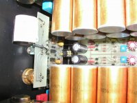
When designing PCBs I wasn't concentrating about the equal spacing of the resistors and caps but about functionality. While designing the front end board I already knew where the input jacks are going to be, from which side the wires from PS would be coming and where the output stage was. So I planned accordingly. I also decided on double sided boards to make connections short. The trimpots are located between the board and chassis. The holes in the back of the chassis allow adjustment without opening the amp. That was very clever in Aleph0. I did my first A75 according to the article in Audio Amateur. In order to change the bias and adjust DC offset I had to open the amp. But then the temperature of the mosfets changed and the readings were chngged too. So here I decided to mount the mosfets (front end board) directly to the chassis and make the access holes. Much easier adjustment. This is how front end board is installed:
When designing PCBs I wasn't concentrating about the equal spacing of the resistors and caps but about functionality. While designing the front end board I already knew where the input jacks are going to be, from which side the wires from PS would be coming and where the output stage was. So I planned accordingly. I also decided on double sided boards to make connections short. The trimpots are located between the board and chassis. The holes in the back of the chassis allow adjustment without opening the amp. That was very clever in Aleph0. I did my first A75 according to the article in Audio Amateur. In order to change the bias and adjust DC offset I had to open the amp. But then the temperature of the mosfets changed and the readings were chngged too. So here I decided to mount the mosfets (front end board) directly to the chassis and make the access holes. Much easier adjustment. This is how front end board is installed:
Attachments
Do you aim for more height than width and depth of the amp
I think that it started with Pass Labs and Madrigal designs but now I favour more hight to the amp. I prefer the footprint to take as little space as possible, all the big amps stand on the floor anyway so why take additional space.
I think that it started with Pass Labs and Madrigal designs but now I favour more hight to the amp. I prefer the footprint to take as little space as possible, all the big amps stand on the floor anyway so why take additional space.
OT: Can't let HPotter's picture pass, mine's worse
Perhaps we should start a thread on the "ultra-clean" rooms us DIY types use to do development work. As pictured on the following link, mine also serves as a darkroom (makes it easy to do PCB's, but cutting fiberglass and other dust cause unmitigated havoc.)
www.tech-diy.com/messiest.htm
To my wife's horror, I also use the Maytag dishwasher to wash the tube equipment I take in from garage sales, hamfests etc.
Transformers
The transformers were custom units from Plitron: 750W with double secondary windings of 34V for output stage and double 52V secondaries for input stage. The sound is quite "remarkable, with a smooth high end and very dynamic low end. It's most vivid characteristic, however, is its low-level detail including ambience cues, which gives a sense of being there, better than any other amp" I had heard. They didn't lie about it in the original article. I can't compare my amps to Alephs (because I didn't complete them yet), but I prefer them to Zen amps of which I have three.
The transformers were custom units from Plitron: 750W with double secondary windings of 34V for output stage and double 52V secondaries for input stage. The sound is quite "remarkable, with a smooth high end and very dynamic low end. It's most vivid characteristic, however, is its low-level detail including ambience cues, which gives a sense of being there, better than any other amp" I had heard. They didn't lie about it in the original article. I can't compare my amps to Alephs (because I didn't complete them yet), but I prefer them to Zen amps of which I have three.
Peter,
I agree the A-75 is a remarkable amplifier. Many diyer's have stayed away from it because of it's complexity, but they don't know what they are missing. I have run the A-75 in bridge mode, and the results are even more amazing.
Have you compared it to new Zen with the Aleph current source?
Jam
I agree the A-75 is a remarkable amplifier. Many diyer's have stayed away from it because of it's complexity, but they don't know what they are missing. I have run the A-75 in bridge mode, and the results are even more amazing.
Have you compared it to new Zen with the Aleph current source?
Jam
I wish I had the patience to do such nice work. When I
want quality construction I have to hire people.
want quality construction I have to hire people.
Building amp like this puts me in a Zen like state of mind so patience isn't usually a problem.😉
- Status
- Not open for further replies.
- Home
- Amplifiers
- Pass Labs
- New amp on a block