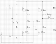
Perhaps I'm missing something, but Q1 and Q3 don't look to
actually be doing anything. Is there an error?
actually be doing anything. Is there an error?
Q1 and Q3 appear to try and affect the ground reference to the power supply. The resistor values seem to be off for this.
Either that or they just pump signal to ground to heat the heatsink. 😉
-Chris
Either that or they just pump signal to ground to heat the heatsink. 😉
-Chris
Edit : okay I see the ground is connected to the speaker through the 220 ohm resistor.
I'm still not sure what that pair does other than drive the 10 ohm resistor. That would stress the power supply. Not sure 5 watts is enough. I would think the effect would be dynamic range compression.
At this moment I am listening to my latest monstrosity, a 2 W / ch Zen-style source-follower amp. But in my memory, the Zen common source circuit sounded better. It seemed to effortlessly and happily give up music, and I had to drive it HARD, all 1 watt of it, to get it to sound bad. This one immediately sounded a little gritty to me, though I've gotten used to it.
Hi, Frank40,
It seems you build something like Crown's Grounded Bridge topology (like used in Crown MA600 or MA1200), where 1/2 power is used to modulate the supply ground (like Hafler's Transnova) + the other 1/2 half is working like normal power amp.
So it is working? How about input impedance? Does it needs powerfull preamp to drive it?
It seems you build something like Crown's Grounded Bridge topology (like used in Crown MA600 or MA1200), where 1/2 power is used to modulate the supply ground (like Hafler's Transnova) + the other 1/2 half is working like normal power amp.
It sounds verry nicely
So it is working? How about input impedance? Does it needs powerfull preamp to drive it?
Hi, Frank40,
My mistake then. You are not building Grounded Bridge topology 😀No erros, Q1 and Q3 whit R9-R12, Is the voltages gain currit.
Voltage gain:
V(speaker)=V(in) * (1+ ( R12/R11) ) (approximately)
That is the way I see it. Interesting idea.
Tom
V(speaker)=V(in) * (1+ ( R12/R11) ) (approximately)
That is the way I see it. Interesting idea.
Tom
Voltage gain:
V(speaker)=V(in) * (1+ ( R12/R11) ) (approximately)
How do you get that? Could you describe how this works?
How many watts this amp gives? In what class, hot classA or cold classAB? Why R11 and R12 is 5watt rating, do they share all the speaker current? Does the supply stays rigid or modulated like Transnova?
You're right. If this is not Crown's Grounded Bridge topology or neither Hafler's Transnova, and works good audio, Frank40 could apply a patent for it 😀That is the way I see it. Interesting idea
Here is my simplified analysis.
Let the input signal be V(in).
V(in) is at the R9,R10,R11 node.
Thus the current I(R11) = V(in)/R11. (eqn A)
This current must return to the supplies via R12.
Thus lets call the voltage at the B1, B2, R12 node V(x).
Then the current through I(R12)= V(x)/R12. (eqn B)
But I(R12)= - I(R11)
Substituting using eqn A and eqn B.
V(in)/R11 = - V(x) /R12.
Then V(x) = -V(in) * ( R12/R11 ). (eqn C)
Also V(in) is at the R13,R14, speaker node.
Let V(out) be the voltage drop across the speaker.
Then V(out)= V(in)-V(x).
Using eqn C for V(x).
Thus V(out)= V(in)-( -V(in) * (R12/R11) ).
Simplifying,
Therefore V(out)=V(in) * (1+(R12/R11)) .
Tom
Hi, Tom,
Thanks 😀 I think I can see this cct as a smart variation of Current Feedback of Hafler's Transnova.
There is something that blurring my view 😀 If it works like you explained, shouldn't +supply powering R1 and -supply powering R4 coming from another supply, rigid towards ground point (not from the same modulated supply B1-B2)?
Tom2 said:Here is my simplified analysis.
Let the input signal be V(in).
V(in) is at the R9,R10,R11 node.
Thus the current I(R11) = V(in)/R11. (eqn A)
This current must return to the supplies via R12.
Thus lets call the voltage at the B1, B2, R12 node V(x).
Then the current through I(R12)= V(x)/R12. (eqn B)
But I(R12)= - I(R11)
Substituting using eqn A and eqn B.
V(in)/R11 = - V(x) /R12.
Then V(x) = -V(in) * ( R12/R11 ). (eqn C)
Also V(in) is at the R13,R14, speaker node.
Let V(out) be the voltage drop across the speaker.
Then V(out)= V(in)-V(x).
Using eqn C for V(x).
Thus V(out)= V(in)-( -V(in) * (R12/R11) ).
Simplifying,
Therefore V(out)=V(in) * (1+(R12/R11)) .
Tom
I just love doing the math of a circuit...thanks for the above Tom!
😎
This is a very interesting CCT 😀 Never seen it done like this before.
Seems the speaker is running openloop. The feedback is only controlling point 2 of the speaker towards leftside of R11.
Point 1 of the speaker seems not to be exactly the same condition as left side of R11. R9 is not equal R13 (Q1 is not biased the same as Q2), plus the mis-matched between Q1 and Q2.
First off this is Frank40's amp so I hope I'm not offending him.
In fact I could be totally wrong in my math.
operation of the mosfets. Ideally R1 and R4 could be replaced with
current souces. Perhaps another supply could work, I don't know.
I also ran a simulation and it shows this.
give the answer.
then the resulting currents flowing into the ground node have to
be equal in magnitude and opposite in sign. I don't see any way the currents could escape via ground.
Again, thanks to Frank40 for his fabulous amp.
Tom
In fact I could be totally wrong in my math.
It seems the supplies do modulate about ground and affect theLumanauw said:
here is something that blurring my view....
operation of the mosfets. Ideally R1 and R4 could be replaced with
current souces. Perhaps another supply could work, I don't know.
I also ran a simulation and it shows this.
Thanks Blues. The trick is to let the math do the work and let itBlues said:
thanks for the above Tom!
give the answer.
I think I'm right. If the nodes are arbitrally assigned voltagesMikew said:
But I(R12)= - I(R11)
then the resulting currents flowing into the ground node have to
be equal in magnitude and opposite in sign. I don't see any way the currents could escape via ground.
I don't think so?Fcarpa58 said:
input impedance very low (1k ?)
Again, thanks to Frank40 for his fabulous amp.
Tom
Hi there
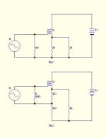
Here is an explanation on how the circuit works. It is really quit simple if we break it down
to it’s most simple form. I won’t go into great details (Languish problem). Compare fig 1 and fig 2 and you will see that all it takes is an extra resistor. (No bias is shown.)
The gain is set buy 1+R1/R2 (approximately).
Now you can place the load directly to the sources on Q1, but the load will affect the response
of the amp. My first amp was build like fig 2. It worked but with no great success.
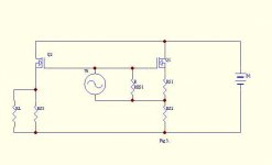
It toke me a while to realize that I had voltage gain if I measured from the power ground to the input, so I just added a Mos- fet more. See fig 3. And now the load is isolated from the gain circuit.
Please feel free to modify the circuit and post your result on the topic.
Sorry for my poor English, but I hope that it helped.
To lumanauw :
I used +/- 25 volt on my amp and I got 25W/ 8ohm out of it. I build it so I cot run hot A/B whit 500mA bias. But you can run it higher, it’s a question of cooling.
Here is an explanation on how the circuit works. It is really quit simple if we break it down
to it’s most simple form. I won’t go into great details (Languish problem). Compare fig 1 and fig 2 and you will see that all it takes is an extra resistor. (No bias is shown.)
The gain is set buy 1+R1/R2 (approximately).
Now you can place the load directly to the sources on Q1, but the load will affect the response
of the amp. My first amp was build like fig 2. It worked but with no great success.
It toke me a while to realize that I had voltage gain if I measured from the power ground to the input, so I just added a Mos- fet more. See fig 3. And now the load is isolated from the gain circuit.
Please feel free to modify the circuit and post your result on the topic.
Sorry for my poor English, but I hope that it helped.
To lumanauw :
I used +/- 25 volt on my amp and I got 25W/ 8ohm out of it. I build it so I cot run hot A/B whit 500mA bias. But you can run it higher, it’s a question of cooling.
Attachments
- Status
- Not open for further replies.
- Home
- Amplifiers
- Pass Labs
- New amp design ?