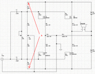
Hi, Frank40,
Thanks for the explenation. It's a very smart CCT 😀
May I ask again how does it sounds. You said like tubes, in what way?
Does it have drawback in loud music volume (clipping behavior)?
I wanted to build this. If I follow exactly your drawing, will it work in very low bias, say only 25-50mA (instead of 500mA)?
Thanks for the explenation. It's a very smart CCT 😀
Do you mean 1+R2/R1?The gain is set buy 1+R1/R2 (approximately).
So the speaker is really in openloop (not included in the Current Feedback loop)? Sometime ago someone proposed a similiar idea (SPLIFF topology), but it ended in quite a debate in solid state forum.And now the load is isolated from the gain circuit.
May I ask again how does it sounds. You said like tubes, in what way?
Does it have drawback in loud music volume (clipping behavior)?
I wanted to build this. If I follow exactly your drawing, will it work in very low bias, say only 25-50mA (instead of 500mA)?
lumanauw said:So the speaker is really in openloop (not included in the Current Feedback loop)?
Sometime ago someone proposed a similiar idea (SPLIFF topology),
but it ended in quite a debate in solid state forum.
I have seen such an amplifier only once before.
Using two output stages, driven in parallel.
The feedback is taken from one of them,
and the other output stage drives the load.
One idea with this,
is that any unwanted injection of signals from load
does not influence the input, through the feedback path.
What are the grounds connected to in the chassis? Are they connected to chassis ground through a thermistor?
Some general notes:
It has been a while since I worked whit the amp. I have been working whit other projects so
my time has been limited, and still is. I do not consider the amp to bee fully developed, it is my hope that I hade raise some interest for this amp. And some of you would like to continue the work.
The amp. needs a regulated power supply for each channel. Due to the grounding offset.
I think it would god idea to disconnect the weir from P2 to the ground, for a greater isolating
between power ground and signal ground. Make R1 variable to adjust the DC offset.
To lumanauw:
Yes your right it’s 1+RS2/RS1, sorry. actually it’s more like 1+RS2/(RS1+1/gm) gm = A/V
How is sounds, well it has been 2 years since I used it. At the time I was using a Vincent CD S3 CD player whit a Tact RCS 2.0 rum correction and Fostex F200A in some ML-TL. The sound was very holographic and open the, bas was very tight compared to tube amps.
You can lower the bias in the gain circuit and use small single mosfets, but you will get cross- over if you lower the bias for the output circuit. Remember it’s run open loop.
To Lineup:
The circuit you mention need more than one stage to obtain voltages gain, you don’t whit my circuit.
To MikeW:
See first Sch. It’s the signal ground.
Best regards
frank40
Thanks for you kind words mr. fscarpa58.
The input impedance is not to low. At first I used the variable output from my test CD player, a standard Sony CD player, whit out any problems.
Frank
The input impedance is not to low. At first I used the variable output from my test CD player, a standard Sony CD player, whit out any problems.
Frank
I have uploaded the Sch. and the Pcb if you interested. It’s in Protel format.
http://rapidshare.de/files/15012338/Frank40_amp.rar.html 102Kb
I made an Error in the Pcb, Both +Vdd and –Vdd is shorted to ground, it has to bee cut fri.
Hope you can use it.
Frank
http://rapidshare.de/files/15012338/Frank40_amp.rar.html 102Kb
I made an Error in the Pcb, Both +Vdd and –Vdd is shorted to ground, it has to bee cut fri.
Hope you can use it.
Frank
It has been a while now, and I was wondering if anyone has tryed to do some work on this amp, any feedback?.
Regards
Frank40
Regards
Frank40
Oh, yes I see.
But input impedance is low too- it is something like common gate. How to drive it? Current output DAC?
But input impedance is low too- it is something like common gate. How to drive it? Current output DAC?
- Status
- Not open for further replies.
- Home
- Amplifiers
- Pass Labs
- New amp design ?

