steenoe said:Yeah, I agree. The amp doesnt look too sexy.
Turn off the light, or close yo eyes.
Voice is sexy, isn't it?
Enjoy 😀
Voices are sexy sounding allright. Infact this amp is really great sounding. I will keep it in the main system for now🙂
Steen😎
Steen😎
steenoe said:Any chance to stack the mainboard on top of the psu?
If yes, you could place it in the most opposite corner.
[/B]
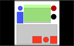
I had been planning on stacking the main board over the psu but with additional height of the 500VA trafo vs 300VA I haven't got the space. The only other alternative I can think of is to mount the main board (indicated in green) onto the back panel as shown in my dodgy drawing of the back panel. The grey boxes are trafo and psu respectively and illustrates the limited space above the psu.
I guess mounting the board like this means I can use ultra short runs from input RCA/XLR's and to the binding posts. 🙄
pj
Attachments
Member
Joined 2002
The one main thing i really like about these aleph's is that you plunk the parts in apply power and it works. If it doesn't then it's for 2 reasons.
1) Bad part's / part.
2) Component in backwards / wrong value/part.
1) Bad part's / part.
2) Component in backwards / wrong value/part.
testing without output boards
After checking the archives I've found a couple of threads describing testing boards without the output mosfets installed. I've jumpered from a point between r15/c4 and c2 to ground on one of my boards to check my work so far.
PSU output is still pretty high - I guess this will drop with the load from the output devices - and is sitting at 30.3V. Voltage drop across R8 is 5.12V (5V service manual figure) , Drop across Z5 is 9.11V (9.1V), Q4 E-C 4.83V ( 4-5V). This all looks pretty much ok.
However, Q5 E-C is only reading 0.63V (4-5V). I'm not sure if this is caused by the lack of output devices or if I should be checking for faults??
anyone able to shed some light on this?
cheers
Paul
edit: I've hooked up the second board and it displays the same behaviour so I'm inclined to think the low reading on q5 is simply due to lack of output boards.
Member
Joined 2002
Re: testing without output boards
Um id like to see these link's I have not heard of any one powering up a aleph with out the outputs installed.
spzzzzkt said:After checking the archives I've found a couple of threads describing testing boards without the output mosfets installed. I've jumpered from a point between r15/c4 and c2 to ground on one of my boards to check my work so far.
PSU output is still pretty high - I guess this will drop with the load from the output devices - and is sitting at 30.3V. Voltage drop across R8 is 5.12V (5V service manual figure) , Drop across Z5 is 9.11V (9.1V), Q4 E-C 4.83V ( 4-5V). This all looks pretty much ok.
However, Q5 E-C is only reading 0.63V (4-5V). I'm not sure if this is caused by the lack of output devices or if I should be checking for faults??
anyone able to shed some light on this?
cheers
Paul
edit: I've hooked up the second board and it displays the same behaviour so I'm inclined to think the low reading on q5 is simply due to lack of output boards.
Um id like to see these link's I have not heard of any one powering up a aleph with out the outputs installed.
SteveA refered the posts earlier in this thread (if I recall rightly) but didn't provide a link...
http://www.diyaudio.com/forums/showthread.php?s=&threadid=72213
the part numbers refer to the aleph5 schematic but by comparing the A5 & A30 service manual with BrianGT's schematic I was able to work out where to jumper.
pj
http://www.diyaudio.com/forums/showthread.php?s=&threadid=72213
the part numbers refer to the aleph5 schematic but by comparing the A5 & A30 service manual with BrianGT's schematic I was able to work out where to jumper.
pj
Sorry that was a follow up thread...
the original with bpd's contribution was here: http://www.diyaudio.com/forums/showthread.php?s=&threadid=48710
pj
the original with bpd's contribution was here: http://www.diyaudio.com/forums/showthread.php?s=&threadid=48710
pj
Have I killed my Aleph???
I've hooked up output boards to one of the mainboards and connected everything up for testing. I have the Aleph30 connected via a 75W light globe in series with the active line.
On initial power-up I had gnd at the output connected to mains earth via PSU gnd. I had assumed this would not cause problems. With the ground connected the light globe was bright with initial current inflow, and then dimmed only slightly. I took this as a probable fault state as in previous test the globe had gone out after initial inflow. I disconnected the gnd from psu gnd/earth and repowered and the light globe stopped glowing after inital current inflow as in previous tests.
I've measured voltages and I'm getting 31.1 from the power supply, same as in unloaded state and current drop across the CRC resistors measures about 14mv so there is almost no current draw from the amp boards.
There is ~ +/-31V present on the main amp board and the V+/V- lines on the output boards. I'm getting almost no measurable voltage between gate/source on Q1 & Q2 and a slowly dropping voltage around 0.5V across Z5. Perhaps I've toasted Z5?
I'm at a bit of loss how to proceed, so any advice would be welcome....
cheers
Paul
Ok I think I have solved the problem, I dawned on me that with disconnected ground the main board was floating at ~31 due to no gnd reference. 
I've hooked safety earth to the chassis base, and run a ground from psu to main board and rechecked both main boards. I now have ~9V over z5. much healthier 🙂
now to hookup the output boards and see if I can generate some heat (not smoke)
pj
I've hooked safety earth to the chassis base, and run a ground from psu to main board and rechecked both main boards. I now have ~9V over z5. much healthier 🙂
now to hookup the output boards and see if I can generate some heat (not smoke)
pj
Pheew, great to hear that you found the fault. I usually measure the voltage drop over the source resistors (doesnt matter which one) when starting up an amp. You should read about 0,5V. I have 0,6 on the Aleph 5.
If you get a too high reading, too much current is running through.
Hope you hear sweet music, pj🙂
Steen🙂
If you get a too high reading, too much current is running through.
Hope you hear sweet music, pj🙂
Steen🙂
back to square one... soon as I hook the psu gnd to the main board gnd the light globe shines brightly and the rails drop to +/- 6.5V...
i'm stumped again.... is this just "normal" current draw causing the globe to shine or do I need to look for a fault???
to clarify slightly - the globe flashy brightly when power is first applied, then drops back in intensity. definitely not a dim glow as described in the literature.
i'm stumped again.... is this just "normal" current draw causing the globe to shine or do I need to look for a fault???
to clarify slightly - the globe flashy brightly when power is first applied, then drops back in intensity. definitely not a dim glow as described in the literature.
damn light globes!! i've wasted hours because I didn't know what to expect!! 😕 At least I should get the other monoblock running in short order.
The slightly less than fully bright glow when the grounds were hooked up actually indicated it was running correctly, but the light globe wouldn't pass enough current to enable the psu to function.
I bit the bullet and hooked up direct to mains, via themistor and slow blow fuse. Not a problem!!
The rails are a little too high at +/-27.7V so I'll have to up the CRC resistors... offset didn't seem tooo bad ~40mv. I couldn't really listen as its after 2am but got the one running monoblock hooked up and playing mp3's off the laptop. The amp seems very quiet - ear right in front of the speaker and no detectable hiss. Bass seems leaner but far more detailed than my old NAD amp. The sinks were quite hot after about 30minutes. 5 seconds was about the limit I could keep my hand on.
I can't wait to get the amps into a cases so I can get down to some quality listening. 😀
Thats a pretty nice figure. Normally the value drops as the amp warms up. Too bad waisting time because of that lightbulb. I have never used it.offset didn't seem tooo bad ~40mv.
Good luck with the next monoblock.
Steen🙂
Well,you´ve learned sommething new today.😉 I usualy try with a light bulb the first time Ipower up.God luck with the rest..🙂Too bad waisting time because of that lightbulb.
Although the lightbulb does not switch to dim glow for classA amps as it does for classAB, it is still useful for current limiting in case there is a fault. Just need to pick the right bulb I guess.
I got the same result with 40,75 & 100w globes. Perhaps globe type and mains voltage play a part?
I do agree it's worthwhile using a globe when powering up. I had found no mention that the usually decriptions of globe behaviour don't apply when using a class A amp. If i'd know that it would have made the procedure a whole lot less painful. 🙄
Anyway I'm just happy that one of the amps is up & running... I had visions of having fried all the mosfets. 😱 I should have the second one going when I get some time tomorrow 😀
Member
Joined 2002
Building the Aleph's with brian's boards is really simple and 100% ready to turn on. I have always just powered my alephs up with out problems. I tried to fix one that had problems ( a friends ) and using a variac wasted time as you can't really power up a aleph slowly. It doesn't work i found this out the hard way. After a certian voltage the output voltage drops the higher you get to the rail voltage it us meant to be at. 🙁 learned something new that day tho.
Hi, folks, I'm having a difficult time obtaining the following caps & resistors:
- C4: CAP 10PF 300V MICA RADIAL
- R0: 3w 5% metal film
- R5: 4.75K OHM METAL FILM .50W 1%
- Diodes: On Semi MUR1560 diodes
Which substitutes are suitable? Digikey is generally not expecting any of these parts for a long time.
For R5, would this resistor work http://www.rpelectronics.com/English/Content/Items/NTE-1_2-4.7K.asp
I was originally going to build an F1 or an A30, but obtaining parts for them is even more difficult, so I've decided on the Mini and have ordered necessary item except the above 4 (and actual casing as well --I'm thinking glass top).
Member
Joined 2002
applebook said:Hi, folks, I'm having a difficult time obtaining the following caps & resistors:
- C4: CAP 10PF 300V MICA RADIAL
- R0: 3w 5% metal film
- R5: 4.75K OHM METAL FILM .50W 1%
- Diodes: On Semi MUR1560 diodes
Which substitutes are suitable? Digikey is generally not expecting any of these parts for a long time.
For R5, would this resistor work http://www.rpelectronics.com/English/Content/Items/NTE-1_2-4.7K.asp
I was originally going to build an F1 or an A30, but obtaining parts for them is even more difficult, so I've decided on the Mini and have ordered necessary item except the above 4 (and actual casing as well --I'm thinking glass top).
I have these parts in stock. If you email me i can send you some. I cant jump on it asap but if needed i can send in a envelope.
Let me know
- Status
- Not open for further replies.
- Home
- Amplifiers
- Pass Labs
- New Aleph Mini PCB GB