Re: A30-A5/A5-A30???
Correction, that's R19 and R21, duhhhh.
However R16 I need to address as well.
Stan
sklimek said:
Hi Mark, Dave - I keep going back and forth wondering which way I am going to go w/ Brian's boards, (A30 or A5) however I might be leaning towards the A5 now. Mark thank you for the updated Excel list for the A5, very helpful, I was wondering if all your part catagories checked out and if in fact C6 was omitted. I've scoured the search archives for R16 & R21 bias adjustments and have saved for reference if this can be of help let me know.
Stan
Correction, that's R19 and R21, duhhhh.
However R16 I need to address as well.
Stan
Stan,
On brians Pcb R12 is AC current gain, R13 Bias, R18 Dc offset.
I have one channel up and running, with standard values I get 20mv Dc on output, 4.58v across Q4 and 5, 0.588v across R35-46, Q1-2 are @ 60 C and my heatsinks are 24 C above ambient,
So yes the parts list that I posted works and I did not fit the A5 C6 that has no location (please don't mix this up with the C6 that is on brians pcb that is for a zenner bypass cap)
Picture will follow but I am busy building the other.
Update on pcbs
As for the pcbs, all current orders are shipped out (including the 2 that came in last week). I am out of power supply boards and have about 15 amplifier pcbs left. If there is more demand for the power supply boards, I can do a reorder.
Order page:
http://www.diyamps.com/aleph/
--
Brian
As for the pcbs, all current orders are shipped out (including the 2 that came in last week). I am out of power supply boards and have about 15 amplifier pcbs left. If there is more demand for the power supply boards, I can do a reorder.
Order page:
http://www.diyamps.com/aleph/
--
Brian
Howdy all,
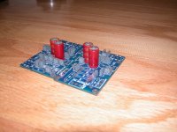
Just thought I'd stop in and say thanks to Nelson Pass and everyone else whose work helped bring these mini-a's to life. The boards look great. I can't wait to fire them up!
I went a little over the top on parts so far, but the Caddocks and Cerafines fit so nicely...🙂 Still waiting on the nonpolar BG cap for the feedback loop, mosfets, etc. I'm thinking that I'm gonna run these minis on batteries. Wish me luck!
PSz.
Attachments
Member
Joined 2002
PSz. said:Howdy all,
Just thought I'd stop in and say thanks to Nelson Pass and everyone else whose work helped bring these mini-a's to life. The boards look great. I can't wait to fire them up!
I went a little over the top on parts so far, but the Caddocks and Cerafines fit so nicely...🙂 Still waiting on the nonpolar BG cap for the feedback loop, mosfets, etc. I'm thinking that I'm gonna run these minis on batteries. Wish me luck!
PSz.
Nice so far. i like those resistor's..
Good job..


Nnnnnnnice! , thats how i would build a chassis also 
and also nice to that board with the caddocks, that looks very good so far 🙂
and also nice to that board with the caddocks, that looks very good so far 🙂
Nice looking monoblocks Mark. Big heatsinks.
Did you build an Aleph 30? or Aleph5 or mini?
PierreG
Did you build an Aleph 30? or Aleph5 or mini?
PierreG
It's alive!!
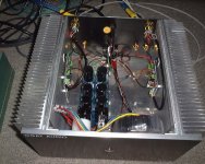
Got my Stereo Mini A up and running today. I had some problems though with one channel (Right), or I guese not quite right.🙂
The Left channel came up on the Variac no problems and settled in around 13mV DC ofset, the rail voltage is 32VDC = +/-16VDC.
The Right channel came up at 200mV DC offset, with the variac.
When I removed the Variac and connected directly to the outlet and powered on the Left channel came up fine, the right channel blew both output FETs..@$&(*&%#*@
Pull the amp all apart replace the 2 FETs and stated all over again, now I get 1.6VDC Offset. What the H*LL IS GOING ON!
I turn off power check my connections and bring the power back up, now the DC offset is 16VDC! Check the FETs they appear to be passing the Rail directly to the output. Take it all apart and recheck everything. Replace the FETs, verify the outgoing ones were dead, yep, toss them out. Look at the board under my scope, all appears fine, wait.. what's this Q1 and Q2 are 200mV apart on the VGS measurement. Seems my 823 and 623 looked similar at 3AM in the morning. Change the 9610, and the IRF140N's reinstall the board, oh yeah the through hole Pad on the source pin one of the outputs is gone due to so much rework...$&*(@&$)
Hardwire it to the 221R resistor, hook up the wire harnesses and bring it up with a variac.. Well I'll be a monkey's Uncle 14mV DC offset.
I had the amp on the test bench with my 6.25R loads, fed the signal generator in the unbalanced input at 1Khx to start. Vin was 2V output was 27.5VDC PTP of course. No ringing, no noise, just a nice clean sinewave from 100hz to 30kHz.
Setup the amp, still running off a variac on my home theatre system, running just fine. Too late to full throttle it, just idiling it at low volume.
Heat.. what can I say, there is none to speak of. The heatsinks are barely reaching warm, even with the dummy loads it barely broke a sweat.
I am not sure what all this concern over heat in Class A amps is all about! 🙂
Well, maybe it has something to do with the size of the heatsinks I used.
One last thing to do, take it off the variac and try it from the outllet. I Installed a CL-30 on the power line to slow power on surging and a 10,000pf ceramic cap across the switch to stop HF arcing. I hope that solves the problem, I certainly do not want to rework that board a 4th time, rather just build a new one.
Here are some pics.
Regards
Anthony
Attachments
Member
Joined 2002
Coulomb said:
Heat.. what can I say, there is none to speak of. The heatsinks are barely reaching warm, even with the dummy loads it barely broke a sweat.
I am not sure what all this concern over heat in Class A amps is all about! 🙂
Well, maybe it has something to do with the size of the heatsinks I used.
LOl
Email me tonight ill mail you out a new board if you like.
Jason

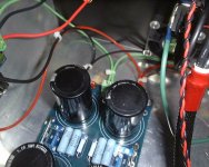
I did have some trouble with the PSU in CRC configuration. I was using 5 x 50R 5W Ohmite rsistors per side = 10R @ 25W.
DC before the resistors under load was 32VDC and after 14VDC across both rails. I tried removing resistors until I got to 25R per side now at 10W and still got only 16.1VDC. I have shunted the Resistors for now with jumpers across the Inductor Pads so I have no CRC or CLC, just plain C. 🙂
I am thinking something in the order of 50R is required or 5x250R
Sigh more Rework...
Attachments
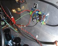
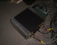
fcel said:And I just noticed that you've got a fan too!?
Well I am popular amoungst my friends, but if your a Fan that's great!
🙂
fcel said:And I just noticed that you've got a fan too!?
Actually this case is a temporary home, sort of a pilot project to determime how much Class A power I could pound inside.
🙂
So what am I getting out of these Mini A's 10Watts?
Fan is not hooked up for this application.
Regards
Anthony
- Status
- Not open for further replies.
- Home
- Amplifiers
- Pass Labs
- New Aleph Mini PCB GB