Nice,
are you going to put on some type of tops and downs or are you just going to leave it open? How hot does it get down there in the summer?
are you going to put on some type of tops and downs or are you just going to leave it open? How hot does it get down there in the summer?
Member
Joined 2002
that looks like a big beast. But looks nice too. why do you have 3 black binding postes per channel ? does it get realy hot. ?
fcel
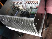
The heatsinks are cast alu. I made the design an had a modelist make a wood pattern, then a local supplier casted the parts.
Then the inner surface and surounding edges were milled.
Dimensions are L 21" W 10" H 2 5/8. The core is somthing less than 5/8", so fins are 2" spaced at 1 1/8"
These parts have the outer surface as casted, only a little cleaning at the foundry.
I have ordered 4 more pieces for future Aleph X. These will be shot blasted on the fin area and then machined.
grataku,
Yes, I will have upper and lower lids, these will be spaced around 3/8 from the heatsink border. I have to find a place that will cut the needed dimensions of alu sheets.
It gets quite hot here in summer up to about 35/37° C inside houses whithout A/C.
I did add a thermal protection (75° C) but i dont think I'll have problems, since the heat sinks goes up about 27° over ambient at the hottest point behind the FET. So I figured that will have about 62/64° in a hot summer day. The power FET are spaced at 1 1/8" over the heatsink.
JasonL
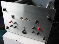
Ya, I knew that those binding post would call attention.
I used what I had at hand. Both upper should be red. I added two pairs because I like to biwire the speakers. The posts are wired individualy up to the star ground and up to the Source/Drain connection at the front end PCB.
Ya, I knew that those binding post would call attention.
I used what I had at hand. Both upper should be red. I added two pairs because I like to biwire the speakers. The posts are wired individualy up to the star ground and up to the Source/Drain connection at the front end PCB.
1/137
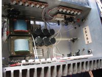
PSU has two home brew trannies rated at 750 VA each. They have a stack of a little more than 3" of EI 150 2% silicone laminations. I'm using only one diode bridge though. Caps are 6x39Kuf, total of over 230Kuf for both channels.
Since i had hum at the speakers I decided to make a CRC filter, so I separated the first two caps and added four power wire wounds at each rail, 4X3.3 Ohms in parallel, I usually go overboard with power disipation on resistors, these are 10W each and needed only about 8W total. After the Pi filter was added hum disapeared from the speakers. If you put your ear inside the box near the trannies you can hear some noise, so nothing to worry about.
Rails are at +- 50V. I do have some imbalance, about 1 V from rail to ground but does not cause any trouble.
Tony,
This is the second time that I have seen somebody in this forum that made the heatsink from scratch. The other person is "carpenter". What is the total cost (US$) of the heatsinks? Is it worth the trouble?
This is the second time that I have seen somebody in this forum that made the heatsink from scratch. The other person is "carpenter". What is the total cost (US$) of the heatsinks? Is it worth the trouble?
apassgear said:fcel
The heatsinks are cast alu. I made the design an had a modelist make a wood pattern, then a local supplier casted the parts.
Then the inner surface and surounding edges were milled.
Dimensions are L 21" W 10" H 2 5/8. The core is somthing less than 5/8", so fins are 2" spaced at 1 1/8"
These parts have the outer surface as casted, only a little cleaning at the foundry.
I have ordered 4 more pieces for future Aleph X. These will be shot blasted on the fin area and then machined.
Very nicely done then. However, remember that there is a huge difference in cooling capacity depending on the surface of the fins. The rougher the surface the worse the capacity. Smoothing them as much as possible should yield good results. The reason is that air molecules get stuck in the roughness and insulate the fins from the air flow.
/UrSv
There is no suppier around Mexico that I know will carry big heatsinks. The other alternative was to import from US but are very expensive and didn't find one suitable for Aleph 4 projects.
What I saw at this forum were small heatsinks, adding 3 or 4 pieces to each side which I din't like either.
I wanted a single piece for each side to have a good structural box and easy to asemble, in my case I only use 8 1/2" screws to bulid the box, and it is suficiently sturdy to carry all the wheight, this amp is very heavy. I guess each heatsinks weighs more tan 16 pound each.
Cost of each, not considering the pattern, was something like $85. including milling the inner surface and all 4 borders.
For mounting components I did all threaded holes at home using a hand elect. drill and manual threading each. I used 6-32 cap screws for all components and no nuts at the heatsinks, and few at other places.
My next set of 4 heatsinks will have the fins shotblasted for a nicer outside finish.
UrSv
I guess your right, but having these pieces sand casted it's difficult to machine or polish each fin and since they are working bautifuly I'll leave them as is.
Thanks for your input
I guess your right, but having these pieces sand casted it's difficult to machine or polish each fin and since they are working bautifuly I'll leave them as is.
Thanks for your input
1/137
Uuuups, Sorry, my rails after the CRC filter are only 44.0 V. The value given before corresponded to DC present at the first set of caps! I haden't mesure this before and it realy took me by surprise. I lost 6V with the filter.
But one good thing, the inbalance came down to less than 0.5V from rail to ground.
The cast surface does have a Lot more surface area than a smooth one. So, maybe that helps. I have to admit that they do seem to always be smooth commercially. I wonder if a very slow fan would make the cast one better than a smooth one with the same fan?
very cool!
I wonder if the sinks costed more or less then extruded ones.
Did you use sand cast foudry? If so Why not make real kewl heatsinks with some kinda drawings or letters(with the fins)??
I wonder if the sinks costed more or less then extruded ones.
Did you use sand cast foudry? If so Why not make real kewl heatsinks with some kinda drawings or letters(with the fins)??
I remember that the Heathkit high power solid state amp, and other Heathkits also used cast alumnium sinks. They always worked well.
I wonder if they could be cast from copper?????
Mark
I wonder if they could be cast from copper?????
Mark
PedroPO said:very cool!
I wonder if the sinks costed more or less then extruded ones.
Did you use sand cast foudry? If so Why not make real kewl heatsinks with some kinda drawings or letters(with the fins)??
Something like the famous Mission 777 🙂
(found a pic http://www.vickers-hifi.co.uk/images/classic/mission777.jpg )
- Status
- Not open for further replies.
- Home
- Amplifiers
- Pass Labs
- New Aleph 4 - heatsinks anyone?