My concern is if I have 1.5 inch baffle and cut the corners I don't have a 1.5 inch baffle anymore, at best there is maybe 7/8 on the very corner and maybe less on the side.
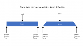
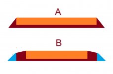
Structurally, it is OK. A panel subjected to an out of plane load (such as air pressure on the inside) can be modelled as a beam. A beam sees the maximum bending moment at the middle. At the edges, the bending is very low. The graphic shows two beams, one a full rectangular cross section, the other with the edges clipped off... Believe it or not, those two beams would have the same load carrying capability, same stiffness, and the deflection would be the same under load.
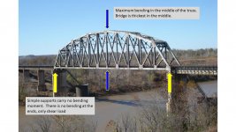
You can see this with bridge trusses. The designers do not make any effort to react bending at the supports, just vertical shear load. It is also done this way because a simple pinned connection is much less susceptible to fatigue.
Attachments
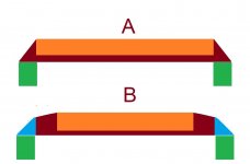
The above is true for speaker cabinets with good bracing and thick walls. It may not be true for lightly built thin-wall designs such as Harbeth or various CLD designs. In those designs, corner bracing is used to (I assume) provide some end-moment fixity to the wall... to make it sort of, almost, cantilevered. The fixity of the corner may be important considering the lack of stiffness in the cabinet wall. But for a well braced thick walled cabinet, the corner provides no meaningful moment reaction.
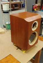
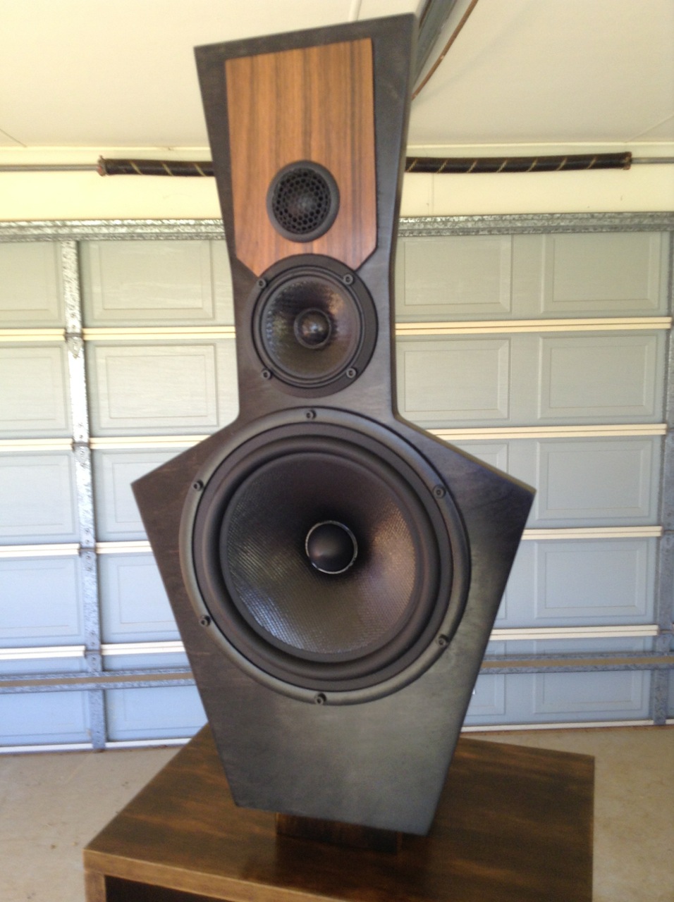
I got the veneer done. It is not perfect, but it is good enough.
First coat of varnish went on this afternoon. I am pleased with how the sapele looks under varnish. I expect I will be starting acoustical measurements within a week. I will have to start with the indoor measurements first, since the weather is not expected to be nice for a while.
j.
First coat of varnish went on this afternoon. I am pleased with how the sapele looks under varnish. I expect I will be starting acoustical measurements within a week. I will have to start with the indoor measurements first, since the weather is not expected to be nice for a while.
j.
Attachments

what about chamfering with 2 x 22.5 deg cuts instead of 1 x 45 deg
A double bevel, or compound bevel, can work really well... I doubt the sound wave can tell the difference between a circular roundover and a compound bevel. My existing speakers have a compound bevel along the top above the tweeter. You can see it in the first post.
Another advantage of the compound bevel is that it addresses Mtidge's concern... it leaves more structure in the corner joint compared to a 45 degree bevel of the same size.
Attachments
Looking nice.I got the veneer done. It is not perfect, but it is good enough.
First coat of varnish went on this afternoon. I am pleased with how the sapele looks under varnish. I expect I will be starting acoustical measurements within a week. I will have to start with the indoor measurements first, since the weather is not expected to be nice for a while.
j.
I can't tell by looking, did you wrap the veneer around both sides and the front? Also what tool do you use to trim? I had the best results (not perfect) using a utility knife with lots of blade changes. My biggest problem is the contact cement or PSA line showing too much.
I did wrap the veneer from the front baffle around the sides. I could not span the entire distance from side - baffle - side because it would have required a 31 inch, and my veneer was 24 inch wide. There is a vertical veneer joint in the centerline of the baffle.
When the panels are orthogonal (standard right angle box), I find trimming to be easy. I place the veneer to be trimmed face down on a table, and I use a veneer saw (see pic) to deeply score the veneer from the back side. Typically I make 4 passes with the saw. This saw has no teeth-set, so it can flush cut without damaging the surface. Then I use a utility knife to finish the cut, which usually takes 3 or 4 passes. The saw excavates the PSA adhesive and scores a groove, and the utility knife follows the groove and makes a clean cut. The table needs to be flat, but it must be a surface which can be scratched and gouged. I finish the trimming with a sanding block.
For curved edges and obtuse angles, I could not make this process work... the best I could do is trim as close as possible with a scissors, and then use a utility knife to trim, millimeter by millimeter. Then careful sanding.
The Veritas flush plane that Fluid talked about looks intriguing. I think I will get one for the next project.
My PSA glue lines show more than I would like... not sure what to do about that.
Attachments

Last edited:
I think you should get the plane and let me know if it is worth it. 😀 For the glue lines I just keep scraping it away with the point of the utility knife until the globs of it are mostly gone. I think this is just a downside of paper backed veneer, the only answer would be using real veneer and glue. I'm avoiding this out of pure laziness.
Lee Valley, maker of Veritas tools, has about everything needed to make beautiful things on their website. Happily there is a store located within 15 minutes of my loft.
EQ won't change the relationship, it will affect all angles equally.But every time we make a DSP filter adjustment, we would have to re-measure the entire listening window again.
I don't want to distract too much from Jim's build but here is the last speaker I veneered. The edges of the front baffle have pre-glued edging all the way round, and the tweeter baffle is 0.6mm rosewood veneer that I attached by putting PVA on the back, letting it dry then ironing on.
The circular cutout to the mid was a total pain and I did it pretty much how Jim describes but I flushed up the front panel to the edges with the flush plane for the final pass. It is one of Veritas's cheapest items but so useful. When you have one it is surprising what you can use it for 🙂
I had to have no visible glue or the stain highlighted it. Warming the glue back up a little then trimming flush in problem areas works quite well as it squeezes out and cuts easier and cleaner.
Attachments

A question on considering baffle width
Since we have had some very helpful discussion on chamfer and bevels on the front baffle, would like to ask one more question on this.
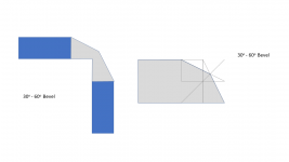
With reference to the image below we have 2 baffles - for baffle A, the chamfer is more abrupt and the baffle width looks easier to ascertain - it is the width of the orange part (please correct me if I am wrong); for baffle B, the gentle bevel starts much earlier - so what would we consider as baffle width - the width of the orange part or the brown part (or even include some of the blue parts)?
Since we have had some very helpful discussion on chamfer and bevels on the front baffle, would like to ask one more question on this.
With reference to the image below we have 2 baffles - for baffle A, the chamfer is more abrupt and the baffle width looks easier to ascertain - it is the width of the orange part (please correct me if I am wrong); for baffle B, the gentle bevel starts much earlier - so what would we consider as baffle width - the width of the orange part or the brown part (or even include some of the blue parts)?
Attachments
You are talking about a rather small difference in the baffle step frequency. If you are doing a simple design then you can probably ignore it. If you are doing full measurements then you'll also discover that the directivity has changed a little, and diffraction has varied a little.
When simulating using the basic diffraction models you would normally set the baffle width as the outer dimensions (green panels) and then choose the size of the roundover or chamfer. Some programs may work differently.
What is often not considered is how the width and depth of the cabinet combined affects the overall directivity. In BEM sims it is possible to view the overall effect on directivity. I posted some simulations showing a similar thing here
Loudspeaker Enclosures are Waveguides
What is often not considered is how the width and depth of the cabinet combined affects the overall directivity. In BEM sims it is possible to view the overall effect on directivity. I posted some simulations showing a similar thing here
Loudspeaker Enclosures are Waveguides
That thread was a real eye-opener for me. You and Patrick Batemen explored an aspect that I had not ever considered up to that point.
EQ won't change the relationship, it will affect all angles equally.
I have thought about this, and of course you are right AllenB... I am not sure how I would use this knowledge in adjusting the DSP filtering on the fly. I suppose I could normalize the on-axis response to the listening window... ? Or somehow normalize out the simulated baffle response?
It is just a lot easier during the iteration phase of filter development to focus on one measurement axis.
Yes! EQ/DSP is a single dimensional line level manipulation - which can never adjust in 3D. So to do something about the sound in 3D... we gotta do something about the baffle, waveguide or drivers.EQ won't change the relationship, it will affect all angles equally.
You know this Jim - I believe in you 😉
Great woodwork by the way 🙂
This is where using a program like Vituixcad makes designing a crossover and using whatever EQ options you have really useful.I am not sure how I would use this knowledge in adjusting the DSP filtering on the fly.
It is just a lot easier during the iteration phase of filter development to focus on one measurement axis.
By taking one good set of accurate time locked polar data at the start you can then see the effect of crossover changes and EQ DSP changes per driver or global and how it affects the on axis, listening window, power response, DI and every individual off axis angle all at once. No need to focus on one axis and keep remeasuring. With an active setup like yours you can work out three different tunings, load the filter settings and see which one you like.
Omni Mic is great for measuring and has some great options, the Hypex Filter designer is woeful though. There is a learning curve with Vituix but it is amazing software and free.
You would have to work out the Q definition of the Hypex EQ with a few transfer function measurements to get it to match but beyond that it should be simple.
I hear that from a lot of folks, but I rather like it. Perhaps because I have never used any of the PC based software or MiniDSP software... Anyway, I like it.the Hypex Filter designer is woeful though
By taking one good set of accurate time locked polar data at the start you can then see the effect of crossover changes and EQ DSP changes per driver or global and how it affects the on axis, listening window, power response, DI and every individual off axis angle all at once. No need to focus on one axis and keep remeasuring. With an active setup like yours you can work out three different tunings, load the filter settings and see which one you like.
Yes, everything you advise is very good guidance.
I like Vituixcad, and I have done a lot of simulations with my existing system.
The strange thing is that when I measure the raw responses of individual drivers and then simulate the effect of my hypex filters in Vituixcad, I get a system response that is close to, but not quite the same as, what I measure as a system response. For instance, a -3 dB Q=2 notch does not have exactly the same measured effect as what is simulated. I found I usually have to increase the dB a little, and decrease the Q a little.
For this project I want to be a little more rigorous about simulating my filters and documenting the results, so I will try a little harder to make it work.
- Home
- Loudspeakers
- Multi-Way
- New active Satori Textreme