I saw some measurements taken in the HTguide forum. Here is the link.. Some Modula Series driver testing...
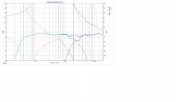
Though tested version is 4 ohm, I kinda trace the FR with a graph tracer programme and modify the sensitivity level to match 8 ohm version approximately. I reworked the crossover also.
The measurements hint towards good behaviour of the driver upto 2.5 kHz and accordingly can be crossed over beyond 2kHz to 2.2 kHz(according to the guy who measured it).
I reworked on the acoustic offset again and came up with this crossover as below
Attachments
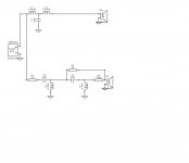
I think the tweeter branch could possibly be simplified but with a risk of low impedance making its presence known. At the same time you could save some money by using smaller capacitors. How does 8.2uf with a 200-300mH inductor and another 8.2 - 15uf plus a resistive L pad measure. You may have to flip the tweeter polarity to get something sensible ?
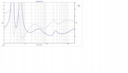
I followed what raymondj suggested. Here are the results. I am not very positive about the Impedance that resulted. What do you guys think? I am also attaching the .dxo (Xover file in Xsim) for tweaking. Thanks
Attachments
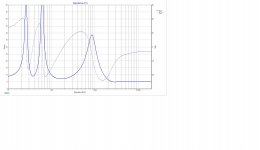

I just tried following your suggestion. Please see the results and opine on the same. What do you think about the system impedance? Thanks
Yes your data is what I expected, and I did foresee the low impedance.
It's at a frequency where most amps should cope. I imagine you have used the L pad to help stabilise the impedance?
I think wait and see what others can do with it or what they next suggest.
Your earlier design would work, this one would work. I think you are getting close to a build and tweaking to what you like. Tweaking the L pad for variations on tweeter level should be easy and cheap. Do a few Sims with slightly more or less level and make a note of the values and buy them so you can easily adjust. The ones you don't use can go to building up your parts collection. I won't be able to do any Xsim for 12 hours or so until I get home tonight.
Thanks raymondj for looking at the results. Take your time and let me know later if you find suitable time to do some Xsim.
Still digging in my failed hard drive for measurements. I had them both for the SS D2604-8330 and Morel CAT378 but my HD died a few months ago.
Again, up to 2.5k LR2 isn't a problem with the 4.8k LCR. You just have to verify the exact notch frequency depending on your exact batch of NE180 to make sure it measures close to factory - there are some production tolerances with these drivers, having measured 12 of them and some of the breakup peaks are scattered around a bit. A few drivers of that batch showed significantly less breakup (probably due to cone formulation tolerances) and didnt need any LCR notch.
Again, up to 2.5k LR2 isn't a problem with the 4.8k LCR. You just have to verify the exact notch frequency depending on your exact batch of NE180 to make sure it measures close to factory - there are some production tolerances with these drivers, having measured 12 of them and some of the breakup peaks are scattered around a bit. A few drivers of that batch showed significantly less breakup (probably due to cone formulation tolerances) and didnt need any LCR notch.
I understand what you are trying to mean. The system impedance is the issue with the XO. I shared the XO files in .dxo format(Xsim). Values of the components are also there. Please help me with an alternative XO design if you have spare time at hand.
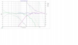
I did have a look at your file and I really couldn't improve on the flat response that you have achieved. The impedance shouldn't worry any reasonably specified amplifier these days. I am fairly confident about the tweeter values and during listening tests you can play around with them to your hearts content.
Ideally I would like to have better phase info and I would like to know more about the NE180 it would be really useful if somebody could give us a frequency response on a known baffle.
The values that Xsim currently gives against the frequency response are quite large in terms of inductance and I cannot help but think it is overkill for such a well designed drive unit. Hopefully others will know better and add their comments. Infact If you look at Pliedka's information in post 20 you can see his 4th order Xover values and they are a fair bit lower than what we are using in the sim. Maybe he could share some further info?
I will have a look around and see if I can find something more about the NE180.
Within your chosen box of 16 litres have you determined what the baffle size will be, as you go further it would be useful info in case somebody models it in your baffle?
Last edited:
raymondj, this driver is quite good as per those who have used it. Here is a link for NE180....
Some Modula Series driver testing...
The person took some measurements which include one taken on a 9 inch wide baffle.
My earlier crossover is complex in tweeter section, but is there any major flaw? If you were to choose between earlier one and the one which I made later on your suggestion... Which one you would select?
I have come up with two design lately. 16 liter bookshelf and a 32 liter MLTL. 16 liter cabinet has a baffle of 14.7 x 9.5 inch and for it I designed XO which are at the first page of this thread.
Last two crossovers are mainly designed for 32 lit MLTL which has a baffle 41.5 x 8.5 inch.
Last two crossovers are mainly designed for 32 lit MLTL which has a baffle 41.5 x 8.5 inch.
In terms of initial selection I would go with the second solution just because it is simpler and cheaper. I start to worry as I get to 15uF capacitors and above 3mH on inductors especially for good quality drivers at the frequencies we are discussing.
I would , build listen, and measure again, then aim to wards final listening and voicing, one component change at a time and listen to varied music sources to get a feel for how well the design copes. If there were issues I would then consider shelving networks or LCRs. Quite often designs do not end up being flat as per the initial sims. Even though modelled, deciding on the first capacitor value for the tweeter takes time for me, no matter what the measurements say. 🙂
I understand the NE180 is a very good value driver, personally I would like some representative measurements with accurate phase for a known cabinet size, or better still using your cabinet dimensions as that would remove any uncertainties. Maybe it will end up as having to import the manufacturers data for the bass and treble units into VirtuixCAD and model the whole system there to answer questions. That would take time.
Do you have the drive units to hand, and is there an audio club or society who would help with some measurements?
Last edited:
Hi guys I used simulation for 4ohm version of the NE180W, so of course my inductance values will be much smaller.
ujju3 I would suggest to use Vituix to get the freq resp with baffle step included for the NE.180W to match whatever transfer function you are aiming for and adjust values manually. You might need the RLC trap, but I'm not 100% certain what might be your case. As for the tweet er section try moving the resistor in series with the second capacitor to the very front , if the impedance value around 2-5kHz is too low. However then the transfer function most likely will change below 6kHz and will have to readjust. Again without actual measured drivers this more of guessing to get some idea, rather than actual x-o design. I very much agree with raymond j point of view - measure, design prototype, listen, measure, make adjustments until the goal is reached.And please remember about the time delay between acoustic centers of the drivers for proper slope integration (phase difference between drivers). Sometimes for proper phase alignment you might want to use sloped baffle or stepped baffle the way Troels did it in his SB 6+1 projects
ujju3 I would suggest to use Vituix to get the freq resp with baffle step included for the NE.180W to match whatever transfer function you are aiming for and adjust values manually. You might need the RLC trap, but I'm not 100% certain what might be your case. As for the tweet er section try moving the resistor in series with the second capacitor to the very front , if the impedance value around 2-5kHz is too low. However then the transfer function most likely will change below 6kHz and will have to readjust. Again without actual measured drivers this more of guessing to get some idea, rather than actual x-o design. I very much agree with raymond j point of view - measure, design prototype, listen, measure, make adjustments until the goal is reached.And please remember about the time delay between acoustic centers of the drivers for proper slope integration (phase difference between drivers). Sometimes for proper phase alignment you might want to use sloped baffle or stepped baffle the way Troels did it in his SB 6+1 projects
Last edited:
I can have the driver unit delivered to my place but there is no audio club here to help me with measurements. I can order Dayton audio iMM6 Or UMM6 (may be if 2nd one is available), but i have not mesured a single thing before. So i really dnt know how much knowledge and skill is needed for measurements.
Some Modula Series driver testing...
Above link has a measurement of the 4 ohm version of the driver in 9 inch wide baffle. My MLT box has 8.5 in wide baffle. I plan to trace that measurement. Then I adjust -3 db over the entire scale to match the sensitivity of the 8 ohm version ( during tracing).
9 inch baffle will give baffle step frequency of 536 hz. 8.5inch will give to 506 hz. So not a big difference.
Can I use this idea and utilize the traced and adjusted graph to design the XO (after extracting minimum phase) ? I will ofcourse use response modeler to model tweeter diffraction . Will this idea work?
Alternatively I can trace Published curve of NE180W-08 (free air) and model it in Response modeler for baffle step, minimum phase and diffraction and the use the results to design the XO.
Which will be a better idea? Dayton iMM6 is easy to work with? Let me know your opinions
Last edited:
Since you are onto passive crossovers, you will have to measure impedance too. A reasonable onboard sound card and some cables, clips and resistors would be minimum requirements for that. Instead of the onboard card, most use a separate USB audio interface with dual channel measurement, full duplex AD/DA and a mic preamp with +48V phantom power. If you have that setup and have done some homework, far more elaborate measurements are within your reach. I'd advise spending on an upgrade path, USB mics really only make sense for room acoustics measurements or adjustments on completed (active) systems.I can order Dayton audio iMM6 Or UMM6 (may be if 2nd one is available)
Those are Greek and Hebrew for me. What is the minimum basic requirements to design a speaker and crossover? What gears I need for that?
I understand. It took me a while too to get modern measurement methods right too.
What you need to understand is that you will have to measure (at least) four sets of data from each speaker driver, being the magnitude and phase data of the response plot and the impedance and phase data from the impedance plot.
These data sets should next be imported in Xsim, VituixCAD or BoxSIM, whichever you like. The reliability of the data sets determines the outcome. Now the problem with USB mikes is that they are not able to reproduce phase info correctly. For there has to be a correlation between output and input signal to acquire the delay and with that the absolute phase.
With response magnitude measurement alone you probably could fix a crossover. Even getting the lowpass and highpass contours right would be possible. Problem is: costs of several crossover versions will be higher than the investment in the right measuring gear, because the only way would be trial and error. You end up with a box of resistors, caps and coils only usable for a next project.
So there was my advice. Get e.g. a Behringer Uphoria 2-channel USB sound card and a Dayton EMM-6. Read a lot about measuring with REW and/or ARTA, or HolmImpulse if you like. Get a few resistors (details in the ARTA LIMP manual), build an impedance measuring bridge and you are set to go. Leave the USB-microphones where they are.
- Home
- Loudspeakers
- Multi-Way
- New 2way bookshelf and crossover