Starting a new project of a 2way bookshelf speaker
Enclosure Details :16 Liter (after excluding volume taken by driver, port tube, and bracings) with a 2 inch diameter x 7 inch long port tube, tuned at 42Hz.
Drivers : 1. Peerless NE180W-08 woofer
2. SB Acoustics SB26ADC tweeter.
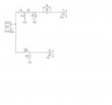
Me and my friend came up with two crossover designs. Crossover frequency is around 1.5kHz-1.6kHz.
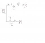
Crossover I :
Enclosure Details :16 Liter (after excluding volume taken by driver, port tube, and bracings) with a 2 inch diameter x 7 inch long port tube, tuned at 42Hz.
Drivers : 1. Peerless NE180W-08 woofer
2. SB Acoustics SB26ADC tweeter.
Me and my friend came up with two crossover designs. Crossover frequency is around 1.5kHz-1.6kHz.
Crossover I :
Attachments
Last edited:
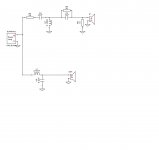
Crossover II:
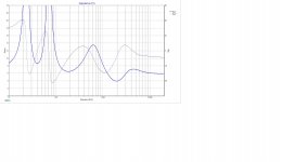
Fs of the tweeter is 680hz. As the crossover point is around 1.5kHZ-1.6kHz, my concern is whether it will be alright to cross the tweeter at such low XO frequency. No plan to play the speaker really loud. What is the chance for distortions to be really worried about at such low XO frequency even if the speakers are not played very loud. Impedance of the First Crossover design appears better to me. Let me know your opinions guys. We used Xsim to design these two crossovers.
Fs of the tweeter is 680hz. As the crossover point is around 1.5kHZ-1.6kHz, my concern is whether it will be alright to cross the tweeter at such low XO frequency. No plan to play the speaker really loud. What is the chance for distortions to be really worried about at such low XO frequency even if the speakers are not played very loud. Impedance of the First Crossover design appears better to me. Let me know your opinions guys. We used Xsim to design these two crossovers.
Attachments
Last edited:
The second filter are more acceptable.
I use the same tweeter cut at ~1KHz and I do not feel distortions at high power but I use 4 order filter.
If you use L-pad for tweeter this must be after first capacitor of tweeter filter to not dissipate energy from low frequency content. Otherwise you will need some very high power resistors.
I use the same tweeter cut at ~1KHz and I do not feel distortions at high power but I use 4 order filter.
If you use L-pad for tweeter this must be after first capacitor of tweeter filter to not dissipate energy from low frequency content. Otherwise you will need some very high power resistors.
FWIW, Troels crosses over that tweeter at 2500 Hhz and he really knows his stuff:
SBAcoustics-61-MFC
A different woofer than yours of course; he used the SB17. Your woofer is a great little unit, by the way; used in several speakers like Jim Holtz' and Curt Campbell's "Statements".
Here's another selection of projects fyi:
SB Monitor SB15NBAC30-8 & SB26ADC-04 - iAMP - DIY way to build Your own amplifier (XO 2700)
Palu (XO at 2100)
Of course, I know nothing about that tweeter or how it sounds, but it looks as if people cross it higher rather than lower, depending on the woofer used.
Geoff
Last edited:
As a rule of thumb I don't mind crossing at 2 - 2.5x the Fs (2nd order). A bit lower when using higher orders. But it really comes down to distortion and the required SPL. As you said, high SPL is not a concearn. And distortion can be measured quite easily with something like a Dayton iMM-6 and free software such as REW.
Edit: I assume you want to cross low to avoid beaming / nonlinear off axis response?
Edit: I assume you want to cross low to avoid beaming / nonlinear off axis response?
Last edited:
Thank you all for you valuable opinions. I have decided to give it a go. DIY is fun because you always have a part which is a bit adventurous.
That is one of the reason. This woofer's response is somehow produces a dip in frequency response between 1.5 to 3 kHz when crossed higher like 1.8 to 2 kHz. So i opted around 1.5 to 1.6 kHz to cross it.
The L-pad in the first xover is a big no-no. It will operate at all frequencies and get HOT. The 2 resistors are strapped across the amplifier's leads essentially.
Number 2 is much better, but I think you can go further...
- The woofer breakup is not attenuated enough, and needs to be suppressed further.
- The woofer will likely benefit from a 3rd order topology to both suppress the breakup and allow the response to be tailored better around the dipping range.
This all said, I've played with the 4 ohm version of the woofer in a xover model or 2, and it was not the easiest to use. The response is rather wobbly, IMO.
The xover lent better to the 1.6-1.8kHz range, so I agree with you on that. I would up the LP coil to 3.3-3.5mH, and your cap is about right. Say- 6.8uF or so. Then, place a 0.1uF cap across the LP coil to help with the breakup.
You picked some good drivers!
Wolf
Thanks Wolf, I further worked up with the XO. Increasing the coil to 3mH for the woofer and put a cap about 0.12 uF across the coil. Let us see what more comes up next.
Hi guys,
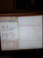
I played some more and utilized the idea from Wolf (thanks man). Here is what came out.
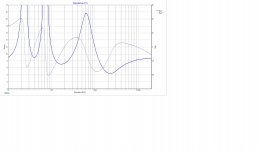
Crossover III:
Please have look and let me know your opinions.
I played some more and utilized the idea from Wolf (thanks man). Here is what came out.
Crossover III:
Please have look and let me know your opinions.
Attachments
I have a bit of experience with the ne180. The problem concerning the dip between 1-2 kHz is the diffraction ripple. You may want to play with the driver placement on the baffle to augment this in your favor. I run this woofer up to 2.5 kHz 2nd order LR with a SS D2604-8330 on a WG. I can't find my xover file but I can tell you the ne180 doesn't show much of the response wiggle you find on the factory published FR graph. Careful flush mounting and chamfering the back of the cutout is necessary to get the most from this driver. Oddly I didn't need much BSC, probably due to the small sealed enclosure I used. This woofer sounds exceptional in a ported design but I chose sealed to make it gel better with subs.
Edit - I just remembered having notched out the 5k peak to keep the tiny bump of increased 3rd order HD out of the summed slope with the tweeter. A 3rd order BW LP would have likely eliminated the need for this, but you can hear it enough with the LR2 LP at higher levels to make it worth your while.
Edit - I just remembered having notched out the 5k peak to keep the tiny bump of increased 3rd order HD out of the summed slope with the tweeter. A 3rd order BW LP would have likely eliminated the need for this, but you can hear it enough with the LR2 LP at higher levels to make it worth your while.
Last edited:
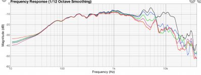
Thank you both. Profiguy can you please try to find your old xo or atleast the FR of NE180 W-08. What do you mean when you say we don't find the the wiggle in case of NE 180W which is shown in factory published FR?
I just copied these 2 graphs to show what I mean. If you look at both graphs, the first one is what DST published. My measurements were more like the second one. There are some issues with cone edge resonance in the 1k area, but my drivers didn't show this so much. Could be that peerless didn't flush mount the driver, but Im not sure.
Attachments

Last edited:
Thanks for your help, but these two graphs are of different drivers. One is 8ohm and 2nd one is 4ohm. Their published FR by the manufacturer also look different. Correct me if I am wrong.
Both graphs are for the ne180w-08, but the 04 version measures pretty much the same aside from the higher 2.83V spl. I've used both and they sound the same to me.
I think the information that profiguy is trying to convey is that the dip you have in the simulation after 1KHz with careful design is nowhere near as bad as it looks in the simulation.
In the real world as long as you are careful with baffle placement to minimise diffraction ripples and also adding 45 degree chamfers to the rear of the baffle you can all reduce this effect. I believe the second graph is purely an example to show a generally flatter response in the area you are worried about. The fact that he mentioned being able to cross over at 2.5Khz second order emphasises his experience with the driver and the point about the 5Khz notch is a good tip.
Both the Peerless and SB acoustics Satori's and probably a few others exhibit the 1KHz cone suspension dip, it looks bad in the manufacturers graphs but once installed and measured with the crossover is is seen at a lesser level and is not a big problem at all.
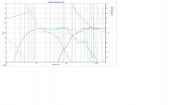
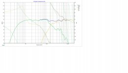
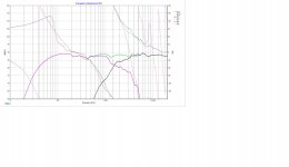
In the image raw woofer and tweeter are red and green, with drivers plus Xover blue.
In the real world as long as you are careful with baffle placement to minimise diffraction ripples and also adding 45 degree chamfers to the rear of the baffle you can all reduce this effect. I believe the second graph is purely an example to show a generally flatter response in the area you are worried about. The fact that he mentioned being able to cross over at 2.5Khz second order emphasises his experience with the driver and the point about the 5Khz notch is a good tip.
Both the Peerless and SB acoustics Satori's and probably a few others exhibit the 1KHz cone suspension dip, it looks bad in the manufacturers graphs but once installed and measured with the crossover is is seen at a lesser level and is not a big problem at all.
In the image raw woofer and tweeter are red and green, with drivers plus Xover blue.
Attachments
Last edited:
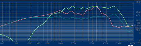
Just playing with Zaph measurements and my measured SB29RDNC to see what is fusible with the NE180W-4. Most likely once everything would be enclosure and drivers measured corrections would have to be made to lined up the phases and other issues for correctly functioning LR4. As for the hole in freq resp around 1.3kHz, trying to linearize the dip with filter shape only made my SB17NRXC sound worse, so your idea about cutting the NE180 around 1.5-2kHz makes sense.
Attachments
- Home
- Loudspeakers
- Multi-Way
- New 2way bookshelf and crossover