Right, the RM7XL didn't use a notched / Chebyshev / Cauer / m-derived / 'ininite slope' / 'NTM' network and tracked relatively conventional slopes (asymmetric 3rd / 4th order) unlike earlier models.
Though if you did them yourself you could ensure they were optimised, yes?I thought as much too.
If you look at the image (figure 6, post #2) that Art posted you can see it's reasonable to expect the kink to stay below -30dB where it isn't really audible. As for phase, it isn't necessarily as steep as the slope (I think I could find an example where it is 2 or 3 orders more shallow than the response suggests).

Has anyone had any experience with the Neville Thiele Crossover, which has notched responses? It is described in the attached US patent (which has expired).
He did a magnificent job of considering phase response and input impedance. His approach can yield a steeper transition than a 4th-order L-R crossover while using the same number of components, at least in the passive versions.
I am considering designing a system using them for my ongoing Klipshorn upgrade project. The KHorn's lower frequency "expiration" point is close to the crossover frequency, so care must be taken not to blow the driver.
I also expect they would have a broad application with direct radiator speakers; I do not know of anyone using them commercially.
Thoughts are appreciated! I think they are worth a look.
Yes, that is a nice crossover function when 4th order overall, but not perfect.
I developed a new family of crossovers that are like that. The article was just published in audioXpress (SEPT 2024 issue). One of my own crossovers is almost exactly like Thiele's 4th order crossover with k=0.500. But I have developed many that are better, but they are not intended for passive loudspeaker crossovers. Only as line level analog active or IIR digital implementations. See aX for more info.
I will be starting a thread about my "DFE Crossover Family" here in the very near future in the Multiway forum. You can PM me for details anytime.
Right. I usually try to keep the stopband peaking ripple at -48dB or <. Not quite 'set in stone', just what I pitch for. Not that it matters, I'd usually aim for a smooth initial rolloff on the electrical transfer function also; it can be easy with these to end up with some excess ripple (similar to a Type I) in the passband, which I'm not so keen on.Though if you did them yourself you could ensure they were optimised, yes?
If you look at the image (figure 6, post #2) that Art posted you can see it's reasonable to expect the kink to stay below -30dB where it isn't really audible. As for phase, it isn't necessarily as steep as the slope (I think I could find an example where it is 2 or 3 orders more shallow than the response suggests).
Looking at the provided response curves, the Neville Thiele Crossover (NTC) topology provides greater attenuation than an LR2 filter in the decade below the crossover frequency.Has anyone had any experience with the Neville Thiele Crossover, which has notched responses?...His approach can yield a steeper transition than a 4th-order L-R crossover while using the same number of components, at least in the passive versions.
In addition, the attenuation rate is better than that achieved by 3rd-order Butterworth (BUT3) low-pass and high-pass filters below and above the crossover frequency, certainly for two octaves or so.
If attenuation of driver cone displacement is of concern, then the response offered by the NTC topology is likely to provide adequate attenuation, with the added benefit of a very narrow acoustic crossover interaction region.
Last edited:
Rod Elliott has an article on the Neville Thiele crossover, including a realization of it that that he devised.https://www.sound-au.com/articles/ntm-xover.htm
Keith
Keith
The review of the RM7XL Special Edition in Stereophile magazine measured the filtered responses of the woofer and tweeter. Those of the woofer displayed some very sharp, lightly-damped, high-level resonances between 7kHz and 11kHz. The peak at around 7kHz was only 15dB or so below the tweeter's output.Right, the RM7XL didn't use a notched / Chebyshev / Cauer / m-derived / 'ininite slope' / 'NTM' network and tracked relatively conventional slopes (asymmetric 3rd / 4th order) unlike earlier models.
Last edited:
@DSP_Geek I noticed that you had very carefully unwound some of the stock inductors to achieve the filter performance that you did. Did you include the DCR of each inductor in your simulations? Your notches are very sharp and deep, so maybe you didn't?You'll find the notch filters will be quite sensitive to component values.
Below the notch we can't be certain, unless we design it ourselves and make it what we want. It would return to full output if not for the driver naturally falling, and the fact that other components are usually used with the notch.Looking at the provided response curves, the Neville Thiele Crossover (NTC) topology provides greater attenuation than an LR2 filter in the decade below the crossover frequency.
Quite. I wouldn't call that one a good design either. 😉 Just for different reasons to the earlier ones.The review of the RM7XL Special Edition in Stereophile magazine measured the filtered responses of the woofer and tweeter. Those of the woofer displayed some very sharp, lightly-damped, high-level resonances between 7kHz and 11kHz. The peak at around 7kHz was only 15dB or so below the tweeter's output.
Thx,Rod Elliott has an article on the Neville Thiele crossover, including a realization of it that that he devised.https://www.sound-au.com/articles/ntm-xover.htm
For me, the appropriate comparison with LR filters is where both NT and LR have the same order....4th order no doubt being the most common.
I got tired or trying to closely eyeball the magnitude differences between a NT 4th and an LR 4th, on the charts in the thread,
so put both filters into a DSP and ran a transfer function between the two.
So for any interested in an easy compare....
LR4 @ 1000Hz is the reference channel. NT4@ 1000Hz is the measurement channel.
High-pass, then low pass.
Personally I can't see an advantage with NT over a simple LR,...... unless I were having potential excursion problems at the low end of the high-pass,
or the notch just happened to help squelch an out-of-band response peak...both being valid utilizations i think
I can't either as-is (and there shouldn't be excursion issues < the HP corner anyway since for a given input maximum excursion for anything > 2nd order occurs above rather than below the crossover frequency). Where these can be useful is when you use them to track a higher order initial slope with (hopefully 😉 ) reduced GD than you'd get if you tracked it via other means. I tend to think they have more value in passive than active systems, but YMMV as always.
The properties that could be taken advantage of appear to be the ability to get a steep slope with...
1. Fewer components,
2. Reduced group delay and
3. Perhaps the ability to tame a peak or reduce excursion at some frequency.
I've seen and used this style to cross woofers while aligning the notch with a breakup peak. Currently the Elsinore speakers use a high pass of this type stating the reason as reduced excursion/distortion.
+1. And it will certainly provide excursion / distortion reduction with the Elsinores since IIRC it's a notched 1st order electrical, so excursion would otherwise be rising < the nominal crossover frequency without that LC increasing the rolloff rate.
@DSP_Geek I noticed that you had very carefully unwound some of the stock inductors to achieve the filter performance that you did. Did you include the DCR of each inductor in your simulations? Your notches are very sharp and deep, so maybe you didn't?
Au contraire, the DCRs were carefully entered from the data sheets and verified by measurement. Moreover, the inductors were unwound to hit the specified resonant frequencies in circuit with the actual capacitors, rather than to a particular value of inductance, and those frequencies were measured in the sim with all other elements out of circuit. I used 1% caps so even if they're off by that much the Q of the tuned circuit won't be too far from spec.
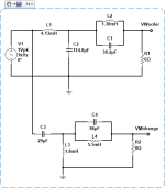
I did a few simulations to get an idea of how this crossover might work. It is idealized; the loads are simply resistors, and the inductors are "ideal." It will give an idea of the design's plausibility, but it does not take into account all of the real-world issues. It is just a starting point for a first look. The design was for a crossover frequency of 400 HZ, and ksq was set to 0.33.
There are some attached thumbnails below.
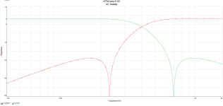
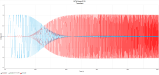
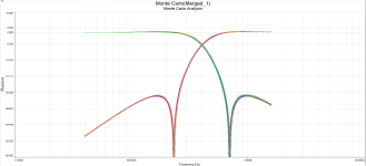
The first is the basic schematic, followed by a basic frequency response. Next a time domain simulation of both outputs, followed by a time domain simulation of the sum of the two outputs. Finally, I did a Monte Carlo with the tolerance on all caps at 5%, and inductors at 3%, which is consistent with the parts available commercially. The design seems plausible, and the summation of waveforms is essentially perfect. The Monte Carlo seems reasonable at first glance. I am in the process of starting to build a coil winder, so I expect that I could reduce the tolerance on the inductors considerably.
Of course, now the devil is in the details, especially taming the woofer's impedance. The real bad news is that a quick shopping cart at a popular vendor shows a total of over $700 just for the parts, no boards or connectors! This may well be why the more elaborate passive crossovers fell from favor.
From an economic standpoint, I could do much better with active filters and small amplifiers.
There are some attached thumbnails below.
The first is the basic schematic, followed by a basic frequency response. Next a time domain simulation of both outputs, followed by a time domain simulation of the sum of the two outputs. Finally, I did a Monte Carlo with the tolerance on all caps at 5%, and inductors at 3%, which is consistent with the parts available commercially. The design seems plausible, and the summation of waveforms is essentially perfect. The Monte Carlo seems reasonable at first glance. I am in the process of starting to build a coil winder, so I expect that I could reduce the tolerance on the inductors considerably.
Of course, now the devil is in the details, especially taming the woofer's impedance. The real bad news is that a quick shopping cart at a popular vendor shows a total of over $700 just for the parts, no boards or connectors! This may well be why the more elaborate passive crossovers fell from favor.
From an economic standpoint, I could do much better with active filters and small amplifiers.
Attachments

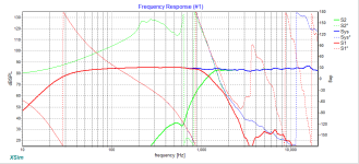
Therein is the [a 😉 ] downside: it can cost. For e.g., this is my Wood Pigeon. Downside: it's a 20 element filter, and there are some big cap values in there (as in 200uF & 100uF in a couple of places). If you don't mind a quality bipolar electrolytics, then it's a bit more affordable; everything is designed to stock Jantzen component values. Still a slow work in progress. I'm normally using LspCAD (or VituixCAD) but still down with the lurgy so not on my main machine & XSim axial is all I've got to hand. Sorry for the graph scale, it's just to show the notches -they'd be off-screen otherwise.
Attachments

I think I'd be looking at it differently.at a popular vendor shows a total of over $700 just for the parts,
Thanks for sharing the results of your design. Seeing the notches showing up so clearly helps confirm the design approach, as does the nicely flat summed response.I'm normally using LspCAD (or VituixCAD) but still down with the lurgy so not on my main machine & XSim axial is all I've got to hand. Sorry for the graph scale, it's just to show the notches -they'd be off-screen otherwise.
Hope that by now you're well on the way to recovery from the lurgy that has hit you.
- Home
- Loudspeakers
- Multi-Way
- Neville Thiele Crossover