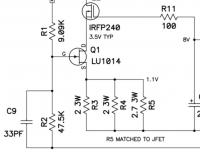
What's the voltage across the resistors that are getting hot? (They're all in parallel, so you can just measure any one of them.)
Also, what's the voltage across the one at the bottom which is also discoloured? (You should read about 21V here.)
You could also check the voltages on the JFET (the small transistor hanging off the board just below the smoking resistors). You should get about 3.5V at the D, and about 1.1V at the S.
Report back with results.
(BTW, Nelson posted the F3 schematic and some other good stuff here: Pictures of a >>GENUINE<< Lovoltech LU1014D Wanted!)
Ok
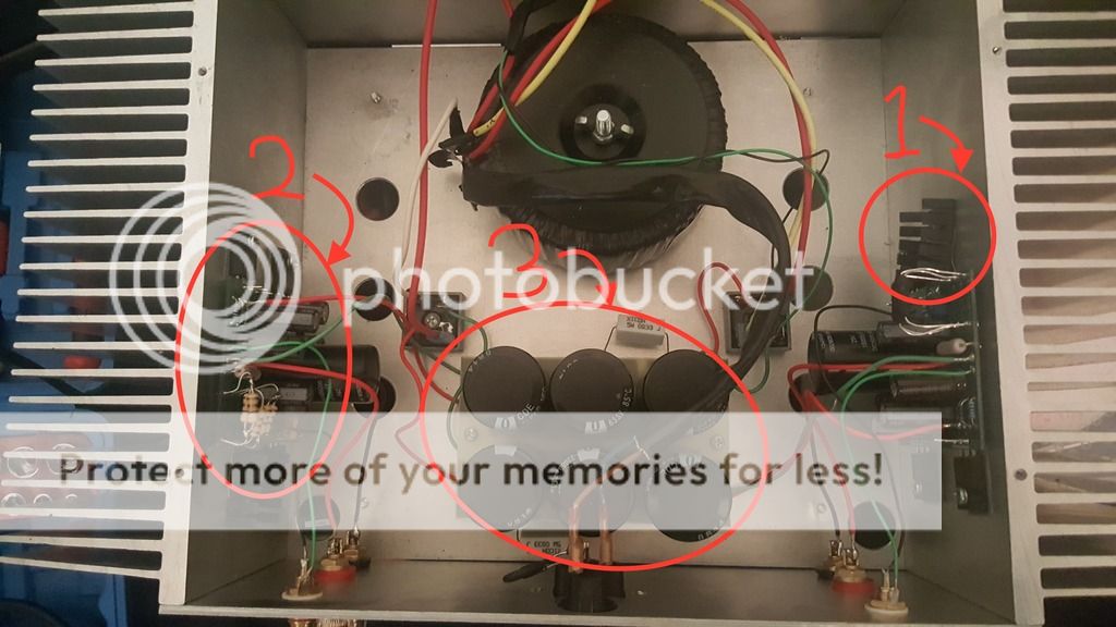
So #1 and all the parts that attach to the heat sink need to be isolated with the small light blue pads, if any metal touches the heat sink it will cause a short?
The blue pad allows heat dissipation but stop electrical current?
#2 The Pcb should be lifted away from the heat sink so as to avoid unwanted contact from the rear solder points to the heat sink?
How should this be achieved as there is limited distance available because of the metal tag lengths that attach the black parts 1 to the PCB?
What is the optimum distance as the PCB always looks close to the heat sink on other amps I have seen?
How could I dismantle and test as the black parts attached to the PCB always need to be attached to the heat sink don't they to avoid over heating?
What is #3 called perhaps PSU??
#3 does seem to have enough clearance from the chasis but should I add more?
Any links to pictures or advice on re build it properly would be could as that is my intention, also should I consider adding any parts?
It is normal to have the PCB mirroring each other or should I turn one of them?
As always thank you for the help, i am really enjoying this Forum I wish I had found it sooner.
Blue pads is only for transistors.
Components like resistors, capacitors etc.
on the pcb's can't touch of conductive heat sinks
Better if your transistors from pcb right side be in the same position of the left one.
Psu resistors is rated 5 watts that little short if you can change
for the same resistance value but more power say rated 10 watts or more.
Twist audio wires outputs RCA and speaker as well. See First Watt excellent quality builds and inspire 😀
Attachments
Read one of 6L6 build threads. It should answer nearly all your questions
Yes
 🙂 Thanks 6L6
The diyAudio build guides
that service is too complicated for complete novice
Yup maybe 2PicoD can restore them for good working and safe.
Cost is small only one zillion $$$$$$$$$$$ me joke 😉
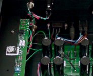
The Lovoltech's heat sinking requirements add to the complication. It has short leads which, I am guessing, is the reason the original builder did not use standoffs.
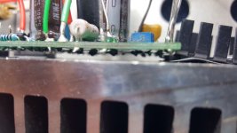
russell66, there should be 4 transistors touching the heat sink. Three identical large ones (IRFP240) and another, much smaller. Could you take a well lit picture of that one? Any changes to mounting the PCB will be restricted by that device.
russell66, there should be 4 transistors touching the heat sink. Three identical large ones (IRFP240) and another, much smaller. Could you take a well lit picture of that one? Any changes to mounting the PCB will be restricted by that device.
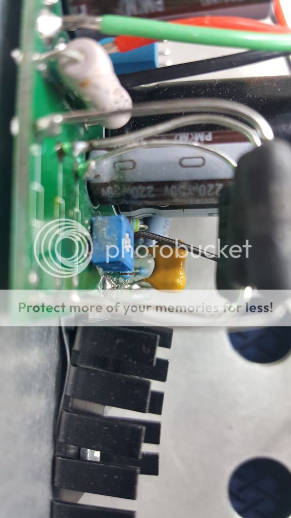
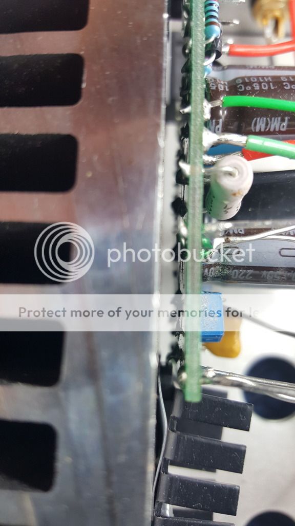
What about blue square trimmer wiper potentiometer position ?
The same visualy or very different ? Is for the bias current ?
More photos please
The same visualy or very different ? Is for the bias current ?
More photos please
It should be for setting Vds across the jfet by adjusting the cascode voltage.
It will also affect the biasing to some extent.
The resistors at the source of the jfet are important to help set the bias.
It will also affect the biasing to some extent.
The resistors at the source of the jfet are important to help set the bias.
Last edited:
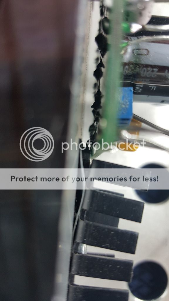
There is definitely clearance all around all though it may not be 5mm.
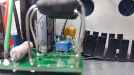
I didn't realize there was a small (i think you called it) transistor under the large metal slotted piece. Which at the front end is in contact with the heat sink.
Is the orange think the J fet? do i measure that with the ohm setting?
The black resistors measure 1.2 on this PCB. I can't get any measurement of the slightly discolored green one, perhaps I have the setting wrong on the meter still using OHM's
The small transistor you just found is the JFET. The three other devices are MOSFETS (just for your information). If the amplifier is playing music, the JFET is likely functional as it is the first gain stage.
Last edited:
Is the orange think the J fet? do i measure that with the ohm setting?
Orange is the silver mica capacitor.
Mesure micro , nano or pico Farads is not in Ohm's.
Well you get one pcb who work.
Let's compare every component on the two pcb's.
Do you see differences ? Verify solder joints one by one is the same like on the good pcb ?
Attachments

- Status
- Not open for further replies.
- Home
- Amplifiers
- Pass Labs
- Nelson Pass F3 amplifier help wanted