SOLD
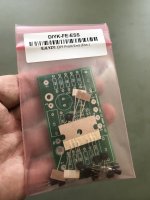
Selling a rare and in-demand front end kit by Papa Pass (click here). This is the original version. $30 shipped in the USA. Paypal payment only.
Selling a rare and in-demand front end kit by Papa Pass (click here). This is the original version. $30 shipped in the USA. Paypal payment only.
Attachments
Last edited:
I just can't help myself, confused as I am about electrons, I keep building the stuff Nelson Pass designs and it works, beautifully! Then again, I always ask before soldering: for the FE 2022, with a bipolar supply (+/- 15V) and single ended input, everything marked VG becomes ground and even -IN goes to ground... Right?
It appears that all the VG are connected together by PCB traces.
You can verify that with a DVM.
Yes, for unbalanced input, connect -IN to VG also.
https://www.firstwatt.com/pdf/art_diy fe 2022.pdf
You can verify that with a DVM.
Yes, for unbalanced input, connect -IN to VG also.
https://www.firstwatt.com/pdf/art_diy fe 2022.pdf
Building is fun, but unbuilding is not so much.
I would suggest instead of 3.3uF, making C2 = 10uF if you have any of them around and they fit the board.
Same for C3, if your load is less than 30k. Otherwise, no biggie.
I would suggest instead of 3.3uF, making C2 = 10uF if you have any of them around and they fit the board.
Same for C3, if your load is less than 30k. Otherwise, no biggie.
Last edited:
Speaking of unbuilding...
I built the boards, connected them to my +/-15vdc PSU, checked all my connections, powered up... no signal gets through.
I am sure of the PSU, it tests fine.
The boards are the newer variety. I used the C6, used the included pot instead of R6, used R13 though it seemed unnecessary, left off R14 and connected nothing to the GF port.
I have single ended input so connected -IN to VG and VG to ground. V+ got +15VDC... V- got -14.9VDC. OUT goes OUT! All the solder joints are fine and yet, no signal gets through. Yes, I checked the signal coming out of my CD player.
Can anyone tell me what I did wrong?
I was going to see if maybe one of the transistors has been incorrectly installed, maybe something got swapped, maybe the J113's are in the wrong holes...but I can't see it from here.. I was going to measure the current through each stage, but my DMM probes won't reach... wish I could help..
You are kind. I’ve checked those things. I checked every component except jfets as they were said to be matched ahead of time. I used close ups of other builds on the right FE2022 thread to select/align leads and holes. I wonder most about grounding and the missing R14 👀
Hi, I wonder if there is someone kind enough to help me out. I really dont have a clue what I am doing and to be honest am really in over my head. I have always wanted to make my own amplifier and have made Mofo and am trying to use DIY FE with it. I ordered the boards from the diyaudio shop and have put it together but I am getting nothing out of it. I have attached a picture of how i have set it up and would be really grateful if someone with more brains than me can look it over and see if i have made any obvious errors.
Thank you.

Thank you.

And what value caps do you have @ C1,C2, and C3? I would think that the intended 3.3uF WIMAs would look something more like this...
 re: cap placement.
@william2001 Many thanks for your help. As you can see from me posting it in the wrong thread that my concentration is pretty bad. I will order some new caps. again. many thanks.